Views: 0 Author: Site Editor Publish Time: 2026-08-26 Origin: Site
Industry metrics consistently reveal a harsh reality in electronics manufacturing. Approximately 60 to 70 percent of all Surface Mount Technology (SMT) defects originate during the solder paste printing process. A minor deviation in paste volume or alignment quickly escalates into costly rework. Treating a First Article Inspection (FAI) merely as a component placement or Bill of Materials (BOM) inspection exercise leaves your production line highly vulnerable. Neglecting rigorous inspection of the paste printing program introduces severe financial and operational risks.
You cannot afford to discover printing errors after the reflow oven. Integrating advanced Solder Paste Inspection protocols into the FAI process is a mandatory requirement. This step validates stencil design, confirms exact paste volume, and dials in printer parameters before you authorize full-scale production runs. By catching deviations at the very beginning of the line, you protect your yield, reduce scrap, and maintain strict quality standards.
Validating the SPI program during the First Article Inspection run is the most effective intervention point for preventing systemic batch defects.
Strict revision control—ensuring the bare board, stencil, and SPI program versions perfectly align—must be the absolute first step of the FAI process.
Transitioning from 2D to a 3D online SPI machine is mandatory for accurate volumetric measurement and true coplanarity assessment.
Effective SPI program inspection requires cross-referencing Gerber data, stencil specifications, and environmental variables (paste storage, expiration, ambient temperature).
Modern SPI systems must feature closed-loop feedback to automatically correct screen printer offsets and correlate data with post-reflow Automated Optical Inspection (AOI) systems.
The primary objective of any First Article Inspection is the 100 percent validation of all physical requirements against the BOM and CAD data. You must ensure the physical build perfectly mirrors the engineering intent. This goes far beyond checking if the right part sits on the right pad. It requires validating the foundation of the solder joint itself. The solder paste deposit is that foundation.
Paste inspection acts as the first critical gate in this First Article Inspection process. It occurs immediately after printing, well before component placement and reflow. If the paste deposit is flawed, the subsequent assembly steps will fail. Contract Manufacturers (CMs) hold a strict accountability here. You must ensure your CM does not bypass paste inspection during FAI to save time. Skipping this step compromises the entire assembly run and invalidates the integrity of the First Article Inspection. We often see operators rush the first board through to the pick-and-place machines, assuming the printer setup is acceptable. This assumption consistently leads to batch-wide failures.
Paste transfer efficiency dictates the mechanical and electrical reliability of the final product. The stencil aperture must release the exact calculated volume of paste onto the pad. Minor deviations in this release compound rapidly. Too much paste causes bridging between fine-pitch leads. Too little paste results in insufficient solder joints or tombstoning during reflow. According to the IPC-7525 stencil design standard, the area ratio—calculated by dividing the area of the aperture opening by the area of the aperture walls—must typically exceed 0.66 for acceptable paste release. If the squeegee pressure is too high, it scoops paste out of larger apertures. If the separation speed is too fast, it causes dog-ears.
The cost-to-repair ratio heavily favors early detection. Fixing a paste defect pre-reflow involves simply wiping the bare board clean and reprinting. This costs pennies. Reworking a fully assembled, reflowed board requires thermal cycles, specialized rework stations, and skilled technicians. It risks damaging adjacent components and degrades the overall reliability of the PCB. Catching these issues at the printer stage is non-negotiable.
Common paste defects caught early include:
Bridging across fine-pitch QFP or BGA pads due to excessive volume.
Insufficient volume leading to open joints on passive components.
Slumping paste that spreads beyond the pad definition before reflow.
Scooping in large apertures caused by excessive squeegee pressure.
Misalignment caused by poor fiducial recognition or physical board stretch.
Legacy 2D inspection systems are fundamentally inadequate for modern high-density PCB assembly. These older systems only measure the area of the paste deposit. They lack any Z-axis height data. This creates a dangerous false confidence. A paste deposit might cover the correct area but be far too thin to form a reliable joint. 2D systems will pass this defect, allowing a guaranteed failure to proceed down the line.
Manual visual inspections are equally unreliable. Human operators cannot accurately gauge paste volume on high-density boards. Components like Ball Grid Arrays (BGAs), Chip Scale Packages (CSPs), and 01005 passives require microscopic precision. The human eye cannot detect a 10-micron height variation across hundreds of pads. Relying on manual checks guarantees that hidden defects will reach the reflow oven. Furthermore, operators experience severe eye fatigue within minutes when staring at highly reflective solder paste under a microscope, leading to high escape rates.
Upgrading to 3D solder paste inspection provides the engineering data necessary for true process control. True 3D systems capture precise volume, height, area, and comprehensive shape profiling. They build a complete topographical map of every single paste deposit on the board using advanced phase shift profilometry.
This 3D profiling identifies complex defects that 2D systems completely miss. It detects dog-ears, where paste pulls up at the corners of an aperture due to poor stencil separation. It identifies slumping, where paste spreads beyond the pad boundaries before reflow. It also catches scooping, where the squeegee blade digs into a large aperture and removes paste from the center. Volumetric data is the only reliable metric for predicting joint reliability.
Inspection Capability | Legacy 2D Systems | Modern 3D Systems |
|---|---|---|
Measurement Metrics | Area, X/Y Offset | Volume, Height, Area, Shape, X/Y Offset |
Defect Detection | Missing paste, severe bridging | Slumping, scooping, dog-ears, insufficient volume |
Process Control | Pass/Fail only | Trend analysis, closed-loop feedback, Cpk tracking |
Suitability | Large components, low density | BGAs, CSPs, 01005, high-density interconnects |
Revision control serves as the absolute foundational check for any FAI process. You must verify that the inspection program accurately aligns with the physical PCB bare board revision. Furthermore, it must match the corresponding stencil revision. A mismatch here guarantees false data and a failed production run. Engineers must cross-reference the Gerber files loaded into the machine with the physical part numbers on the floor.
Registration accuracy relies heavily on fiducial recognition. The machine must locate the board precisely. You must verify both global and local stretch or shrinkage compensation. PCBs can warp or distort slightly during fabrication. The inspection program must dynamically adjust its measurement grid to match the physical reality of the specific board being inspected. If the Gerber data assumes a perfectly flat, dimensionally perfect board, but the physical FR4 has stretched by 2 mils across a 10-inch span, the inspection system will flag false positional errors.
Setting the right tolerance thresholds during the First Article Inspection run dictates the success of the entire shift. You need a strict framework for setting Upper Control Limits (UCL) and Lower Control Limits (LCL). These limits apply to both volume and height. Referencing the IPC-7525 stencil printing standard, industry baselines often start at ±40 percent for volume, but fine-pitch components demand tighter constraints. Engineers aim for a Process Capability Index (Cpk) greater than 1.33, indicating a highly capable and stable printing process.
False calls, or false rejects, create massive operational friction. If the machine flags good boards as defective, operators lose trust in the system. You must tune the program during FAI to balance strict quality control with production throughput. Adjusting lighting parameters, refining pad definitions, and optimizing measurement algorithms will drastically reduce false calls without letting actual defects slip through. Engineers should review the histogram data for the first 5 to 10 boards to center the process window.
Software and hardware are only part of the equation. Comprehensive material checks must occur before the very first print. You must verify solder paste lot numbers and expiration dates. Proper storage conditions are non-negotiable. Review the refrigeration logs to ensure the paste remained within specified temperature ranges.
The formal FAI sign-off must include tracking thawing times. Paste used too cold will not roll properly on the stencil. Paste left out too long will degrade and dry out, changing its thixotropic index. You must also log mixing and conditioning procedures. Ambient temperature and humidity on the production floor directly impact paste viscosity and tackiness. Documenting these environmental variables ensures the process remains repeatable.
Material Variable | Inspection Action During FAI | Impact on Print Quality |
|---|---|---|
Paste Expiration | Check jar label against BOM and MES. | Expired flux causes poor wetting and weak joints. |
Thawing Time | Log removal time from refrigerator (typically 4-8 hours prior). | Cold paste causes incomplete aperture filling and skipping. |
Ambient Humidity | Record floor humidity (target 40-60% RH). | High humidity causes paste to absorb moisture, leading to voids. |
Mixing Protocol | Verify automated mixing time (e.g., 2 minutes at 1000 RPM). | Improper mixing leaves flux separated from alloy powder. |
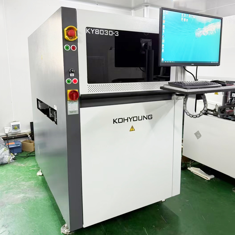
When evaluating high-end inspection capabilities, engineers often look to the Kohyoung SPI machine as an industry-standard benchmark. This architecture demonstrates what is required for zero-defect manufacturing. You need to analyze the core features that drive measurement accuracy.
Dual-projection Moiré interferometry is a critical feature. It uses multiple light projections to eliminate shadows cast by adjacent tall components or warped boards. Warp compensation algorithms dynamically adjust the Z-axis reference plane. This ensures the machine measures the paste height relative to the actual pad surface, not an assumed flat board. Shadow-free inspection zones guarantee that every single pad receives accurate volumetric measurement. The system must calculate the zero-reference plane dynamically for every field of view to maintain precision.
High-mix, low-volume production environments demand flexibility. You must evaluate the necessity of inline integration versus offline batch testing. A 3D online SPI machine provides real-time process control. It catches drift immediately. Offline systems introduce delays and allow defective boards to queue up before detection.
Software capabilities dictate the speed of New Product Introduction (NPI). You need rapid Gerber-to-program conversion speeds. The software should integrate seamlessly with your parts management database. An intuitive user interface reduces programming time and minimizes operator error. Fast changeovers are essential when running multiple different First Article Inspections in a single shift. The machine should support automatic conveyor width adjustments via barcode scanning to eliminate manual intervention.
Machine-to-Machine (M2M) communication transforms inspection from a passive check into an active control system. Closed-loop feedback is a critical value driver. The inspection system feeds X, Y, and Theta offset data directly back to the screen printer using IPC-CFX standards. The printer then auto-corrects its alignment for the next board. This prevents defects before they happen.
Integrating inspection data into Manufacturing Execution Systems (MES) provides full traceability. It automates compliance reporting and archives the exact paste volume for every serialized board. Furthermore, you must look for synergy between inspection stages. Correlating pre-reflow paste data with post-reflow 3D AOI data validates the entire FAI process. It allows engineers to isolate the exact root cause of a defect, whether it was a printing issue, a placement error, or a thermal profile problem.
A major risk during NPI is that complex 3D programming delays the First Article Inspection release. If the machine takes hours to program, the entire SMT line sits idle. This destroys production schedules and increases overhead costs.
To mitigate this, utilize offline programming software. Engineers can generate and debug the inspection program on a separate workstation while the line is running another product. Standardizing component library templates also accelerates program generation. When the new board arrives at the line, the program is already complete and ready for minor tuning. You should maintain a centralized server for all inspection programs to ensure version control across multiple lines.
Inspection machines can lose accuracy over time due to thermal expansion, mechanical wear, or optical degradation. This calibration drift leads to invalid FAI approvals. If the machine measures incorrectly, your process control is an illusion.
Establishing strict Gage R&R (Repeatability and Reproducibility) protocols is the primary mitigation strategy. You must utilize automated calibration targets provided by the manufacturer. Maintain routine instrumentation checks. Schedule daily or weekly inspection routines using a known glass calibration artifact to ensure the Z-axis measurements remain perfectly accurate. If the machine fails the daily calibration check, the line must stop until maintenance realigns the optics.
Operators quickly develop alert fatigue if a poorly tuned program generates excessive false defects. They will start blindly accepting warnings just to keep the line moving. This skill gap and behavioral risk completely negate the value of the equipment.
You must mandate an engineering-level sign-off on program tuning during the FAI phase. Do not hand the program over to line operators until the false call rate is minimized. Provide continuous training on how to interpret volumetric data. Operators need to understand the difference between a harmless variation and a critical process failure. They should know how to read a 3D topographical map on the machine interface to verify if a flagged pad is truly defective.
A First Article Inspection remains incomplete and highly vulnerable without a verified, optimized 3D inspection program and strict revision control. Relying solely on post-reflow checks guarantees higher rework costs and lower overall yield. Validating the paste deposit before component placement is the most effective way to secure your manufacturing process.
When upgrading your technology, focus on true volumetric accuracy and shadow-free measurement. Prioritize systems that offer closed-loop printer feedback and seamless MES compatibility. The ability to correlate pre-reflow paste data with post-reflow AOI data provides the ultimate diagnostic tool for process engineers. False-call reduction through intelligent software algorithms will keep your production line running smoothly.
Take the following actions to improve your current process:
Audit your current FAI standard operating procedures to ensure mandatory volumetric paste inspection is included before component placement.
Implement strict logging for all solder paste environmental variables, including thawing times, ambient temperature, and humidity.
Request recent Gage R&R reports from your equipment vendors to verify the ongoing measurement repeatability of your current systems.
Transition all new product introductions to offline programming workflows to eliminate machine downtime during the FAI phase.
A: SPI measures solder paste volume, height, and alignment before component placement and reflow. AOI inspects component placement, polarity, and final solder joint quality after reflow. Together during FAI, they provide complete defect coverage by validating the foundation (paste) and the final result (the joint).
A: 3D inspection provides critical volumetric data that 2D systems lack. It measures the exact height and shape of the paste deposit. This prevents hidden reflow defects, such as insufficient solder on fine-pitch BGAs, which 2D area-only measurements consistently miss.
A: Modern machines reduce false calls using advanced algorithms, dynamic warp compensation, and dual-projection lighting. These features eliminate shadows and adjust for board warpage. Proper FAI program tuning by engineers also refines pad definitions and tolerance limits, ensuring only true defects trigger alerts.
A: Programming requires Gerber files for pad locations, CAD data for coordinates, and stencil files to understand aperture dimensions. Integrating BOM data helps define specific component tolerances. Offline software uses this data to automatically generate the inspection parameters before the board reaches the line.
A: Closed-loop systems send real-time X, Y, and Theta offset measurements directly back to the solder paste printer. The printer uses this data to continuously and automatically correct its alignment. This prevents drift and stops printing defects before they occur, drastically improving yield.
A: Revision control ensures the bare PCB, the stencil, and the inspection program are all the exact same version. Mismatched revisions lead to false measurements and guaranteed defects. Verifying this alignment is the mandatory first step of any FAI process.
A: Per the IPC-7525 standard, industry-standard baselines typically range from ±40% to ±50% of the target volume. However, these limits depend heavily on component pitch. Fine-pitch components like 01005s or micro-BGAs require much tighter tolerances, often around ±25%, to prevent bridging or insufficient joints.