Views: 0 Author: Site Editor Publish Time: 2026-08-14 Origin: Site
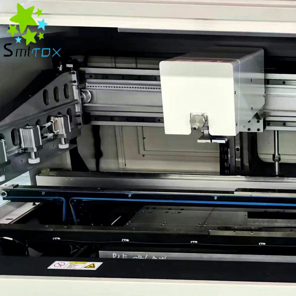
Industry consensus shows 60% to 70% of Surface Mount Technology (SMT) defects originate during the solder paste printing phase. Skipping First Article Inspection (FAI) causes cascading failures across the production floor. These failures lead to heavy rework, scrapped boards, and delayed production schedules. Relying solely on downstream Automated Optical Inspection (AOI) to catch printing errors happens too late. The printed circuit board has already passed through pick-and-place machines and reflow ovens by the time AOI flags an issue. A rigorous FAI protocol acts as a hardware-dependent process rather than a simple procedural formality. Evaluating and selecting the right equipment dictates the reliability of your first article inspections. A highly capable PCB Printer Machine ensures precise solder deposition before mass production begins. We will explore how hardware mechanics, vision systems, and closed-loop integration drive first-pass success.
Defect Prevention Over Detection: First Article Inspection shifts quality control to the earliest possible stage, drastically reducing downstream rework costs by pausing production immediately after the first print.
Hardware Dictates Repeatability: The mechanical rigidity, vision system accuracy, and squeegee control of your PCB printer machine are the primary drivers of first-pass success.
Closed-Loop Integration: Modern automatic stencil printers must seamlessly integrate with Solder Paste Inspection (SPI) systems to provide actionable data for immediate offset corrections.
Process Standardization: Successful FAI requires strict environmental controls, documented approval workflows, and controlled change rules before releasing a line for mass production.
First Article Inspection establishes a strict quality baseline before mass production begins. Engineers use this phase to confirm accurate solder paste deposition across every single pad on the bare board. The primary objectives include verifying paste volume, height, area, and precise alignment. Operators evaluate the printed board against predetermined engineering tolerances. Passing the first article inspection proves the machine setup, stencil design, and paste condition meet the required standards. You cannot achieve reliable solder joints without hitting these specific metrics during the initial print. A single missing deposit on a micro-BGA pad guarantees a functional failure at the end of the line.
Timing dictates the effectiveness of First Article Inspection. The SMT line must pause immediately after the machine prints the first board. The light tower should turn red, signaling a hard stop. Operators must transfer this board directly to the inspection station. You must prevent a queue of unverified boards from entering the pick-and-place machines. Running continuous prints before validating the first article defeats the purpose of the inspection process. Immediate action isolates potential setup errors. It stops the line from manufacturing hundreds of defective assemblies while waiting for the first board to exit the reflow oven.
Catching a printing error immediately after the first print saves significant time and materials. Operators simply wipe the wet paste off the board, clean it with an approved solvent, and reprint. Discovering insufficient paste or bridging after the reflow oven introduces severe financial penalties. Hardened solder defects require manual rework using soldering irons or hot air stations. Thermal stress from rework damages sensitive components and degrades the FR4 PCB substrate. High-density boards often become complete scrap if reflowed with severe printing errors. Early detection eliminates these downstream financial burdens and protects your component inventory.
Strict inspection protocols satisfy rigorous industry standards. Automotive manufacturing requires IATF 16949 compliance, while general electronics rely on ISO 9001 frameworks. Both standards demand absolute traceability and documented process control. FAI establishes a documented baseline for the entire production run. Quality managers log the inspection results, machine parameters, and environmental conditions. This documentation proves the manufacturing process remained under control from the very first board. It provides necessary evidence during customer audits or field failure investigations. Without a logged first article, you have no proof that your process started within acceptable control limits.
The initial mechanical steps heavily influence the first print quality. The sequential workflow begins with automated PCB loading via edge conveyors communicating through SMEMA protocols. Stepper motors drive the board into the exact printing zone. The machine then executes a precise alignment routine using optical sensors. Finally, the board lift sequence raises the substrate to meet the underside of the steel mesh stencil. These mechanical movements must operate smoothly. Jerky movements or inconsistent lift speeds disrupt the alignment and cause the board to strike the stencil aggressively.
Board stability during the squeegee stroke prevents printing defects. Machines utilize edge clamping, top clamping foils, and vacuum support blocks to secure the substrate. Magnetic support pins placed strategically under heavy components prevent board flex when the squeegee applies downward pressure. A perfectly flat board maintains a tight gasket seal against the stencil. Poor clamping allows the board to bow. This bowing causes solder paste to bleed under the stencil apertures, creating bridges between adjacent pads. The rigidity of the Z-axis table directly dictates the quality of this gasket seal.
Advanced vision systems prevent rotational and X/Y axis offsets. Dual-roving cameras scan the fiducial marks on both the PCB and the stencil simultaneously. The machine's software utilizes complex recognition algorithms to calculate the exact offset. The motorized alignment table then makes micro-adjustments to perfectly align the board pads with the stencil apertures. Accurate fiducial recognition guarantees the paste lands exactly where intended. Modern systems use coaxial and ring lighting to illuminate different substrate colors and finishes.
Engineers evaluate vision systems based on their ability to handle challenging substrates. The cameras must process poor contrast fiducials caused by oxidized copper, HASL finishes, or thick solder mask. The system must also compensate for warped boards by calculating stretch factors. High-density interconnect (HDI) substrates demand extreme alignment precision. The vision system must reliably align apertures for micro-BGA components and 01005 passive packages. Weak vision algorithms cause inconsistent alignment, leading to immediate first article failures and constant operator intervention.
Solder paste exhibits thixotropic properties. Its viscosity changes under mechanical stress. The squeegee blade applies shear force to the paste during the print stroke. This action kneads the solder paste, lowering its viscosity and allowing it to flow smoothly into the stencil apertures. Once the squeegee passes, the paste recovers its higher viscosity to hold its shape on the pad. Controlling the squeegee speed ensures the paste achieves the correct thixotropic state for a flawless first print. A standard starting speed sits around 25mm to 40mm per second, depending on the paste chemistry.
Modern equipment utilizes motorized, programmable squeegee pressure systems. These systems outperform legacy pneumatic cylinders. Motorized controls provide closed-loop pressure feedback. Load cells monitor the downward force in real-time. The machine automatically adjusts the Z-axis to maintain consistent pressure across the entire stroke length. Consistent pressure ensures uniform aperture fill. Too much pressure scoops paste out of large apertures and causes rapid squeegee wear. Too little pressure leaves apertures partially empty and leaves a thick film of paste on top of the stencil.
The method used to separate the board from the stencil impacts paste release. The speed and distance of this board separation require precise control. Engineers program specific snap-off profiles based on the paste type and aperture sizes. A slow initial separation, typically 0.1mm to 0.5mm per second for the first millimeter, allows the paste to release cleanly from the aperture walls. The machine then accelerates the drop to minimize cycle time. Proper separation mechanics leave sharp, well-defined paste deposits resembling perfect bricks.
Poor snap-off mechanics cause severe printing defects. If the board drops too quickly, the paste tears. This tearing leads to "dog-ears" or peaking, where the paste forms sharp points that can cause shorts during component placement. Smeared prints occur if the board shifts laterally during separation. Evaluating the rigidity of the board lift mechanisms ensures the Z-axis drops perfectly straight. High-end machines offer highly customizable separation profiles to mitigate these risks, allowing multi-stage drop speeds tailored to specific stencil thicknesses.
Manufacturing facilities must contrast fully automatic stencil printer platforms against semi-automatic and manual printing methods. Manual clamshell printers rely entirely on operator skill for alignment, squeegee pressure, and separation speed. Semi-automatic machines automate the squeegee stroke but still require manual board loading and visual alignment using a monitor. Fully automated platforms remove human variance entirely. They handle loading, vision alignment, printing, wiping, and unloading through programmable recipes stored on the factory server.
Scalability heavily favors automated solutions. Semi-automatic machines introduce high labor costs and cycle time limitations. Operators become fatigued, leading to inconsistent prints toward the end of a shift. In high-mix, low-volume (HMLV) environments, automated machines reduce changeover times through saved digital recipes and motorized conveyor width adjustments. In high-volume environments, they maintain continuous throughput without operator intervention. The operator-dependency risks associated with legacy methods make them unsuitable for modern, fine-pitch electronics manufacturing where tolerances are measured in microns.
Closed-loop feedback represents a massive leap in process control. An automated printer communicates directly with 3D Solder Paste Inspection (SPI) machines via factory network protocols. The SPI machine scans the printed board and measures the exact X/Y offset, volume, and height of every paste deposit. It then sends this data back to the printer. The printer's software analyzes the trends and automatically adjusts its alignment table for the next board, keeping the process centered.
This integration drives significant efficiency. Auto-correcting X/Y offsets removes operator guesswork. The printer also uses SPI data to trigger automatic under-stencil wiping. If the SPI detects a trend toward bridging or paste smearing, it commands the printer to perform a vacuum wipe cycle immediately. This real-time adjustment during the first article run and subsequent production ensures the process remains within engineering limits. It prevents defects before they violate quality thresholds, drastically reducing the need for manual inspection.
Measuring solder paste volume stands as the only reliable predictor of solder joint reliability. Legacy 2D inspection systems only measured the area of the paste deposit. Area measurements ignore the height of the paste. A print might cover the entire pad area but lack sufficient height, resulting in a weak, solder-starved joint. 3D SPI systems calculate the true volume by multiplying the area by the measured height profile. Volume dictates the mechanical strength and electrical conductivity of the final connection.
Engineers establish strict acceptance thresholds based on industry standards like IPC-7525. A typical control limit requires the paste volume to fall between 80% and 120% of the theoretical aperture volume. During FAI, quality technicians verify the first board meets these baseline control limits. If the volume falls outside this window, operators must adjust squeegee pressure, speed, or separation profiles before running the second board. Height limits usually sit between 90% and 110% of the stencil thickness.
Understanding the root causes of printing defects allows operators to implement immediate cures during the first article run. The following table maps common symptoms to their mechanical or environmental origins.
Defect Type | Root Cause Analysis | Corrective Action (Cure) |
|---|---|---|
Bridging | Underside stencil wiping failures, excessive squeegee pressure, or poor gasket seal between board and stencil. | Adjust programmable snap-off speeds, increase vacuum wiping frequency, and verify board support pins. |
Insufficient Paste | Clogged stencil apertures, incorrect squeegee speed, or dried paste lacking proper thixotropy. | Verify paste kneading cycles, audit steel mesh aperture design, and replace expired solder paste. |
Slump | Environmental temperature spikes, high humidity, or incorrect paste flux formulation. | Enforce strict climate control in the facility and verify paste expiration and thawing logs. |
Dog-Ears / Peaking | Board separation (snap-off) speed is too fast, causing the paste to tear instead of releasing cleanly. | Decrease the initial snap-off speed in the machine recipe to allow smooth paste release. |
Smearing | Lateral movement of the board during the drop sequence or worn squeegee blades. | Inspect board clamping mechanisms for wear and replace damaged polyurethane or metal squeegees. |
Scavenging (Scooping) | Squeegee pressure is too high, or the squeegee blade material is too soft for large apertures. | Reduce squeegee pressure and switch to a rigid metal blade with a 60-degree attack angle. |
Even the most advanced hardware will fail if the steel mesh stencil contains flaws. Improper stencil tension causes the mesh to sag during the print stroke. This sagging destroys the snap-off mechanics and leads to smeared prints. Damaged apertures with burrs or rough edges trap solder paste, causing insufficient volume on the pads. Residual cured paste from previous runs also blocks apertures and ruins the gasket seal. Stencils lacking proper nanocoatings often struggle to release paste from area ratios below 0.66.
Facilities must incorporate strict stencil inspection into the FAI setup checklist. Operators must measure stencil tension using a dedicated tension gauge before loading it into the machine. The tension must meet the manufacturer's specifications, typically between 35 and 45 N/cm. Furthermore, technicians must perform ultrasonic cleaning inspection. Inspecting the stencil against a backlight reveals any blocked apertures. Rejecting compromised stencils before the first print saves hours of troubleshooting on the line.
Temperature and humidity fluctuations drastically alter solder paste rheology. Solder paste consists of metal alloy powder suspended in a flux medium. High temperatures cause the flux to thin out, leading to paste slump and bridging. Low temperatures make the paste stiff, preventing it from rolling smoothly ahead of the squeegee. High humidity causes the hygroscopic flux to absorb moisture, which boils during reflow and creates solder balls across the substrate.
Mitigating these risks requires strict environmental controls. The SMT facility must maintain climate-controlled enclosures, targeting 22°C to 25°C and 40% to 60% relative humidity. Material handling procedures are equally critical. Operators must follow proper paste thawing procedures, allowing refrigerated paste to reach room temperature naturally for at least four hours before opening. Strict adherence to paste out-of-refrigeration lifespans prevents operators from using degraded materials that will fail the first article inspection.
Human error remains a significant adoption risk. Operators bypassing automated checks invalidate the entire FAI process. Improperly loading the stencil, failing to secure the board support pins, or ignoring SPI warnings leads to immediate defects. Lack of understanding regarding machine parameters causes operators to make incorrect adjustments when troubleshooting a failed first article. Guessing at squeegee pressure settings ruins stencils and wastes expensive solder paste.
Management must outline a standardized training framework. Training should focus heavily on tooling setup, emphasizing the importance of a flat board surface. Operators must understand how to select the correct squeegee angle and material for different paste types. Training must cover interpreting SPI feedback. Operators need the skills to translate volumetric data into specific machine adjustments, such as altering pressure or wiping frequency, rather than just clearing the alarm and continuing production.
Process control relies on rigid documentation. Releasing the SMT line for mass production requires completing several inspection steps. Facilities must establish a strict sequence to ensure nothing gets missed during the setup phase.
Technicians compile product records matching the PCB part number to the correct machine recipe and stencil revision.
Operators verify key setup checks, including squeegee condition, support pin placement, and paste lot numbers.
The machine prints the first board, and the operator immediately transfers it to the SPI machine.
The physical inspection evidence from the SPI machine is logged and saved to the factory server.
A quality engineer reviews the SPI data and physically signs off on the first article before the operator switches the machine to continuous production mode.
Facilities must establish containment protocols for failed first prints. If a board fails, operators must isolate it, clean it, and log the failure reason. They cannot simply tweak a setting and run another board without documenting the change.
Evaluating mid-to-high-tier equipment requires mapping specific mechanical features to production outcomes. Using the GKG PCB printer as a benchmark reveals the capabilities necessary for high-yield manufacturing. High-end platforms feature automatic stencil positioning. This eliminates manual alignment errors when loading a new product. The machine uses its vision system to locate the stencil fiducials and locks it into the exact required position without operator pushing or pulling.
Intelligent wiping systems represent another critical feature. Advanced machines offer programmable wet, dry, and vacuum wiping combinations. They track wiper paper consumption and alert operators before the roll runs out. Paste roll height monitoring uses lasers or optical sensors to measure the diameter of the paste bead on the stencil. If the bead shrinks below a critical threshold, the machine automatically dispenses more paste or pauses to alert the operator. This prevents insufficient volume defects caused by paste starvation.
Procuring premium printing hardware requires balancing the initial capital expenditure against long-term operational savings. High-end machines deliver ROI through drastically reduced defect rates. Catching errors during FAI and maintaining closed-loop control minimizes the labor hours spent on manual rework. It also reduces the volume of scrapped PCBs and wasted electronic components. Automated paste dispensing and efficient wiping systems minimize solder paste waste, lowering consumable costs month over month.
Shortlisting equipment requires matching machine capabilities to specific production requirements. Facilities running high-volume consumer electronics prioritize rapid cycle times and dual-lane conveyor configurations. Facilities assembling complex aerospace or medical devices prioritize extreme accuracy. They need machines capable of printing solder paste for metric 0201 or 01005 component sizes. The chosen platform must possess the mechanical rigidity and vision resolution to support the smallest apertures on the production schedule.
First Article Inspection remains the most critical quality gate in SMT manufacturing. Its success is fundamentally tied to the precision and reliability of the printing hardware. Relying on downstream inspection guarantees higher rework costs and lower factory yields. Catching defects at the source protects your production timeline and your material investments.
Selecting the right equipment requires evaluating core mechanical criteria. Robust vision alignment, programmable squeegee and snap-off controls, stable board clamping, and seamless SPI integration form the foundation of a capable printing process. Upgrading legacy manual or semi-automatic systems to fully automated platforms removes human error and standardizes your quality output.
To optimize your solder paste printing process, take the following next steps:
Request a live demonstration running your most complex board design to evaluate the machine's handling of HDI substrates.
Demand SPI data from the trial run to verify volumetric repeatability and ensure the machine meets IPC-7525 standards.
Verify software compatibility with your existing factory execution systems to enable closed-loop communication.
Audit your current stencil cleaning and tension measurement protocols to eliminate tooling-related defects.
Establish a strict, documented approval workflow that physically pauses the line until the first article passes inspection.
A: The primary goal is to verify paste volume, height, area, and alignment before mass production begins. This process prevents downstream reflow defects. It requires immediately pausing the SMT line after the first print to inspect the board, ensuring the machine setup and stencil meet engineering tolerances.
A: It prevents bridging through precise mechanical controls. Programmable snap-off speeds ensure clean paste release. Accurate stencil alignment and stable board clamping maintain a tight gasket seal. Automated under-stencil vacuum wiping systems remove residual paste that causes shorts between adjacent pads.
A: Automatic printers remove human error from the equation. They provide closed-loop SPI feedback, automated fiducial recognition, and motorized squeegee pressure control. These features guarantee the extreme precision and repeatability required for micro-components, which semi-automatic machines cannot consistently achieve.
A: Kneading alters the thixotropic properties of the solder paste. The squeegee motion applies shear force, lowering the paste's viscosity. This allows the paste to flow smoothly into the steel mesh apertures during the first print, preventing insufficient volume defects.
A: Wiping frequency is determined during First Article Inspection and adjusted based on SPI data. Fine-pitch components may require wiping every three to five boards. Closed-loop systems automatically trigger a wipe cycle if the SPI detects a trend toward paste smearing or bridging.