Views: 0 Author: Site Editor Publish Time: 2026-09-12 Origin: Site
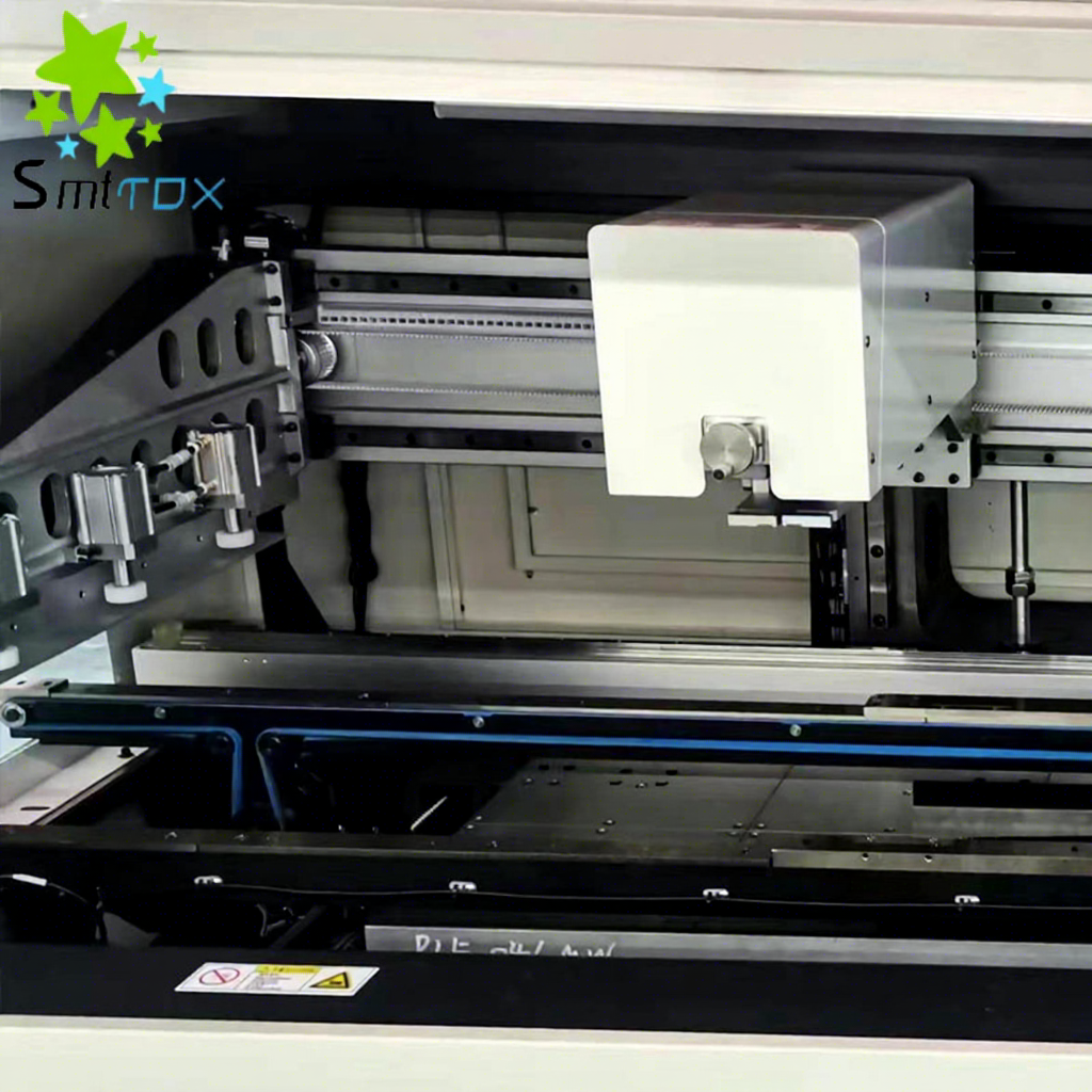
Asymmetrical layer stacks, heavy copper planes, and thermal excursions during fabrication inevitably cause varying degrees of PCB warpage. Substrate deformation—presenting as bow or twist—creates a severe mechanical challenge at the start of surface mount technology (SMT) assembly. When a board fails to sit perfectly flat, it compromises the stencil-to-board seal, known as gasketing. Poor gasketing directly correlates with high SMT defect rates. A microscopic gap between the stencil foil and the copper pad allows solder paste to bleed under the apertures, causing bridging on fine-pitch components. Conversely, uneven separation leads to insufficient paste volume. These printing errors inflate defect rates, eroding production margins and forcing intensive manual rework. While manual workarounds like taping exist for prototyping, high-yield production lines require systemic intervention. An advanced PCB Printer Machine mechanically and algorithmically neutralizes warpage before paste deposition.
Gasketing is Critical: Effective warpage compensation restores the flush contact between the stencil and the PCB, preventing solder paste from bleeding under the stencil apertures.
Hardware Interventions: High-precision printers utilize dynamic Z-axis control, programmable vacuum tooling, and advanced edge clamping to physically flatten warped substrates during the print stroke.
Software and Vision Integration: Modern equipment uses 2D/3D optical inspection and algorithmic offset adjustments to align apertures dynamically, compensating for stretch or distortion caused by board flattening, while also monitoring for stencil warpage.
Equipment ROI: Investing in a capable automatic stencil printer directly reduces rework costs and improves end-of-line yield, justifying the capital expenditure for high-mix or complex assemblies.
Industry standards like IPC-A-600 define acceptable limits for bare board deformation. For standard SMT applications, the maximum allowable bow and twist sits at 0.75%. As component miniaturization pushes toward 01005 and 0201 metric packages, even warpage within this tight tolerance disrupts the printing process. The baseline success metric for a modern assembly line is achieving less than 50 PPM defect rates. Hitting this target requires equipment that handles substrate irregularities without sacrificing paste volume consistency.
Boards warp due to fundamental material behaviors. The primary driver is a Coefficient of Thermal Expansion (CTE) mismatch. Different materials within the substrate stack expand and contract at different rates during curing or reflow, building internal stress. Asymmetric designs make this worse. A board featuring a solid copper ground plane on one side and sparse signal traces on the other will naturally bow. Improper storage conditions also play a role. When FR4 material absorbs moisture from high humidity, it warps before reaching the assembly line.
A warped board fundamentally alters paste transfer mechanics during the print cycle. With concave warpage, the board edges sit higher than the center. When the squeegee applies downward pressure, the stencil fails to contact the center pads fully. This gap allows solder paste to bleed outward, causing bridging and shorts. With convex warpage, the center sits higher than the edges. The squeegee forces the stencil down, but upon release, the board springs back prematurely. This early separation pulls paste out of the apertures unevenly, leaving insufficient solder volume on the pads.
Here is a breakdown of how warpage direction influences specific print defects:
Warpage Type | Physical Behavior During Print | Primary Solder Paste Defect | Downstream SMT Failure |
|---|---|---|---|
Concave (Edges High) | Poor center gasketing; stencil floats above pads. | Paste bleed, smearing, excessive volume. | Bridging, shorts on fine-pitch ICs. |
Convex (Center High) | Premature snap-off; board springs back early. | Insufficient volume, dog-ears, clogged apertures. | Dry joints, open connections, tombstoning. |
Twist (Diagonal) | Inconsistent squeegee pressure across the stroke. | Variable volume across different board quadrants. | Unpredictable yield, localized rework requirements. |
Volume inconsistencies at the printing stage cascade into severe downstream failures. Paste bleed creates physical bridges that short out adjacent pins on fine-pitch components. Insufficient volume leads to dry joints or open connections. Uneven paste deposits cause uneven wetting forces during reflow. This imbalance physically pulls small passive components upright, creating tombstoning. Catching these errors after reflow requires expensive manual rework and risks thermal damage to surrounding components.
Securing a distorted substrate requires more than standard edge rails. High-precision machines deploy motorized top-clamps and side-snuggers. These mechanisms grip the board edges firmly without encroaching on the printable area. Ultra-thin foil clamps provide a secure hold while maintaining a near-zero profile, preventing the squeegee blade from catching on the hardware. This secure perimeter establishes the foundation for stabilizing a warped board.
Internal support handles the actual flattening. Programmable vacuum support blocks and dedicated tooling pins manipulate the board's topography. For convex warpage, vacuum blocks actively pull the center of the substrate down against a rigid support matrix. For concave warpage, strategically placed tooling pins push the sagging center upward. This combination of pulling and pushing forces the substrate into a temporary, artificially flat state.
The sequence for stabilizing a severely warped board typically follows these steps:
Edge Capture: The conveyor stops the board, and side-snuggers align it against the fixed rail.
Z-Axis Elevation: The tooling table raises the vacuum blocks and support pins to meet the underside of the substrate.
Top Clamping: Motorized foil clamps deploy over the board edges to lock the perimeter in place.
Vacuum Engagement: Programmable vacuum zones activate, pulling the warped sections flat against the tooling matrix.
Verification: The vision system confirms the board is flat and ready for the print stroke.
Different warpage profiles require specific tooling strategies. Here is a comparison of common tooling options used to stabilize substrates:
Tooling Type | Primary Function | Best Used For | Limitations |
|---|---|---|---|
Magnetic Support Pins | Provides rigid upward support against squeegee pressure. | Concave warpage, heavy boards, double-sided assemblies. | Cannot pull down convex warpage; requires manual placement. |
Programmable Vacuum Blocks | Pulls the substrate flat against a rigid matrix. | Convex warpage, thin substrates, flex-rigid boards. | Requires clear areas on the bottom side to achieve a vacuum seal. |
Dedicated Routing Fixtures | Custom-machined plates that cradle the entire board. | Extreme warpage, high-volume dedicated product lines. | High cost, zero flexibility for high-mix production environments. |
Motorized Foil Clamps | Secures the top edges of the board to the conveyor rails. | Edge curling, stabilizing the perimeter during snap-off. | Reduces printable area slightly at the board edges. |
The Z-axis movement dictates how the board meets the stencil and how it separates. Precision Z-axis motors control the exact separation speed, known as snap-off. A controlled, multi-stage snap-off prevents defects on warped boards. If the board releases too quickly, the sudden spring-back effect smears the paste. A slow, controlled separation ensures the paste releases cleanly from the aperture walls, preventing dog-ears and paste bumps.
Squeegee pressure must adapt to the board's condition. Closed-loop squeegee pressure systems use load cells to monitor and maintain consistent downward force. As the squeegee travels across the uneven topography of a heavily warped board, the system dynamically adjusts the pressure. This ensures the blade wipes the stencil clean across the entire surface, depositing the correct amount of solder paste into every aperture, regardless of localized high or low spots.
Flattening a warped board introduces dimensional stretching. When a bowed board is forced flat, the distance between the pads changes slightly. High-resolution digital microscope cameras measure the exact position of the board's fiducial marks. The machine compares these actual coordinates against the expected Gerber data to calculate the exact degree of dimensional distortion.
Once the stretch is calculated, the machine adjusts the X, Y, and Theta alignment of the stencil to match the new, temporary pad locations. This dynamic offset ensures the apertures align perfectly with the stretched substrate. Advanced vision systems also perform stencil warpage detection. They monitor the stencil foil to ensure the upward pressure from a warped PCB has not permanently deformed or stretched the metal mask during the print cycle.
Accurate printing requires massive structural rigidity. A cast-iron or heavy-duty welded frame prevents machine-induced vibration from exacerbating print inconsistencies. When dealing with warped boards, the machine applies significant physical force via vacuum blocks and clamps. A rigid frame ensures this force flattens the board rather than flexing the machine itself.
Motor precision directly impacts alignment accuracy. Linear motor drives paired with sub-micron optical encoders provide the necessary repeatability. When the vision system calculates a microscopic offset to compensate for board stretch, the motors must execute that adjustment flawlessly. Standard belt-driven systems often introduce backlash, compromising the precise alignment required for distorted substrates.
Hardware capabilities rely entirely on intelligent software. Operators need intuitive interfaces to program specific vacuum sequences and clamping pressures. A heavily warped board might require a staged vacuum pull-down to avoid micro-cracking the substrate. Advanced software allows engineers to build custom warpage profiles for specific board designs.
Effective warpage compensation software should include:
Programmable vacuum zones that activate sequentially to prevent board stress.
Customizable snap-off profiles that adjust separation speed based on paste viscosity and board thickness.
Automatic fiducial stretch compensation algorithms that recalculate X/Y offsets in real-time.
Data logging capabilities to track warpage trends across different board batches.
Validating the print quality immediately prevents downstream defects. Machines equipped with built-in 2D or 3D inspection systems offer a massive advantage. These systems scan the board immediately after separation. They verify paste volume, detect bridging, and identify scooping. This immediate feedback loop validates the effectiveness of the warpage compensation parameters before the board moves to component placement.
Using a high-tier machine as a benchmark illustrates these concepts in practice. A GKG PCB printer represents the industry standard for handling severe warpage in high-volume environments. These machines integrate specialized wiper systems that keep the stencil underside clean, which prevents paste smearing from warped boards. They utilize advanced 2D inspection to catch defects instantly. Their flexible tooling configurations allow operators to rapidly deploy targeted vacuum support, neutralizing complex twist and bow deformations effectively.
Implementing advanced warpage compensation introduces specific production realities. Advanced clamping, multi-stage vacuum stabilization, and multi-point vision checks add seconds to the overall cycle time. Production managers must balance throughput requirements with the necessity of zero-defect printing. While the printer operates slightly slower, eliminating downstream rework and scrap results in higher overall line efficiency and better yield.
An automatic stencil printer handles the mechanical flattening, but complementary stencil design remains necessary. Step-down stencils accommodate localized warpage around heavy components. Nano-coatings applied to the stencil foil improve paste release, mitigating the risks associated with premature snap-off on convex boards. Optimized aperture designs, such as rounded corners, ensure consistent volume transfer even under suboptimal gasketing conditions.
To maintain the accuracy of warpage compensation systems, facilities must implement strict maintenance protocols. A pcb printer machine cannot compensate for board distortion if its own mechanical baseline is compromised.
Z-Axis Tramming: Verify the parallelism between the tooling table and the stencil frame monthly using a precision dial indicator.
Vacuum System Cleaning: Inspect and clean vacuum hoses and support blocks weekly to prevent solder paste or flux residue from degrading the suction force.
Squeegee Calibration: Calibrate the load cells on the squeegee head quarterly to ensure the programmed pressure matches the actual physical force applied to the stencil.
Vision System Verification: Run a glass calibration plate through the machine to verify the accuracy of the fiducial stretch algorithms and camera alignment.
Clamp Inspection: Check the motorized edge clamps for wear and replace the ultra-thin foils if they become bent or damaged, as this will cause uneven edge sealing.
Operator training is equally critical. Technicians must know how to correctly configure vacuum blocks and tooling pins. Improper placement on a severely warped board creates stress concentrations, leading to micro-cracking in the FR4 substrate or damaging internal traces.
To effectively neutralize the impact of substrate deformation on your assembly yield, implement the following action steps:
Audit your current defect data to identify specific product lines suffering from paste bleed or insufficient volume caused by poor gasketing.
Evaluate your existing printing equipment for programmable Z-axis control, closed-loop squeegee pressure, and dynamic vacuum tooling capabilities.
Schedule a proof-of-concept trial with a vendor using your facility's most severely warped bare boards to test mechanical flattening and algorithmic alignment.
Integrate built-in 2D or 3D post-print inspection to validate paste volume immediately after the print stroke.
Train your operators on the correct placement of vacuum blocks and tooling pins to prevent substrate micro-cracking during the clamping process.
A: Standard IPC tolerances dictate a maximum bow and twist of 0.75% for SMT applications. Advanced printers push this boundary using specialized vacuum tooling and aggressive clamping. However, extreme warpage exceeding 1% introduces severe risks for downstream component placement, even if the printing stage succeeds.
A: Taping the board to the back of the stencil is a manual workaround only viable for low-volume prototyping. In production environments, it introduces unacceptable variability, causes paste bumps upon manual separation, and creates massive cycle-time delays. It cannot replace automated mechanical clamping.
A: Squeegee pressure adapts the blade to uneven topography. A closed-loop, programmable squeegee system ensures the blade conforms to the stencil over the warped substrate. This dynamic pressure prevents paste skipping in localized low spots and stops the blade from scooping paste out of high spots.
A: Automated machines utilize vacuum pull-down, motorized edge clamping, and algorithmic vision alignment to dynamically adapt to board topography. Manual stencil fixtures are rigid and unadjustable. They cannot flatten the board or compensate for the dimensional stretch that occurs when a warped board is forced flat.
A: No. While advanced printing solves paste deposition issues like bridging and opens, it is only the first step. A board forcibly flattened during printing springs back to its warped state upon release. This spring-back can still cause component shift or tombstoning during the reflow process.