Views: 0 Author: Site Editor Publish Time: 2026-10-09 Origin: Site
Picture this scenario on a busy manufacturing floor. A high-volume production run is in full swing. Placement machines are firing at maximum speed. Suddenly, a flashing red light brings the entire line to a halt. The culprit is a single misaligned printed circuit board at the very beginning of the assembly process. Such seemingly minor feeding errors cause catastrophic downtime, expensive component damage, and severe production bottlenecks.
Often operating quietly at the front of the line, the board loading equipment is the true unsung hero of the Surface Mount Technology assembly process. The absolute foundation of a high-yield, profitable manufacturing line is a smooth, uninterrupted supply of bare boards. Maintaining this stable board feeding does not happen by accident. It requires a sophisticated combination of precision mechanics, smart sensor technology, and proper equipment selection. This comprehensive guide explores how automated loading systems achieve unwavering stability. We will outline practical troubleshooting strategies for common feeding issues and highlight the critical features to evaluate when upgrading your production facility.
Precision is Key: Modern loading systems utilize advanced optical sensors and stepper motors to ensure exact magazine alignment, effectively preventing jams and double-feeding scenarios.
Technology Matters: Deciding between a traditional pusher-type and a vacuum suction mechanism depends heavily on your specific board thickness, material, and susceptibility to surface scratches.
Line Synergy: For peak operational efficiency, the loading unit must communicate seamlessly with downstream equipment via standard SMEMA protocols.
Proactive Maintenance: Routine sensor cleaning and mechanical calibration are non-negotiable practices for maintaining long-term feeding stability.
Smart Purchasing: When selecting new equipment, prioritize concrete specifications like multi-pitch selection, intuitive touch screens, and heavy-duty frame construction.
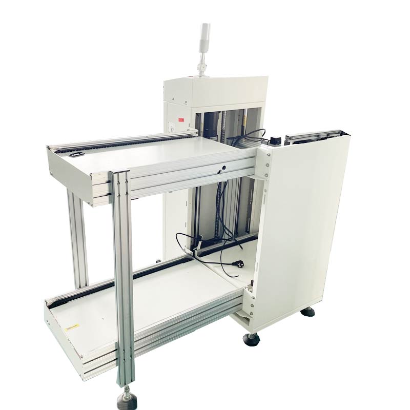
At its core, an smt pcb loader is an automated machine designed to seamlessly feed bare printed circuit boards from a stacked magazine rack directly into a solder paste printer or a connecting conveyor. By acting as the gatekeeper of the entire manufacturing line, this equipment dictates the initial rhythm and pacing of the process.
The true cost of feeding instability extends far beyond a momentary pause in production. When a board enters the line at a slight angle or off-tempo, the ripple effects are immediate and costly. Solder paste printers misalign their stencils, leading to poor solder joints. Downstream, pick-and-place machines fail to recognize fiducial marks. This results in component misplacement or total machine stoppage. Stalled boards left sitting on conveyors cause solder paste to dry out, leading to inevitable rework and scrapped materials.
Transitioning from manual board handling to a fully automated system effectively eliminates these risks. Human operators introduce variables such as inconsistent loading speeds, physical misalignment, and the ever-present danger of electrostatic discharge. An automated system removes human error from the equation entirely. It handles each substrate with calculated delicacy and ensures a perfectly consistent cycle time that keeps downstream machines operating at their maximum theoretical throughput.
Achieving flawless board transfer requires a symphony of mechanical and electronic components working in perfect harmony. The internal architecture of a modern pcb loader machine relies on three foundational pillars to guarantee stability on the shop floor.
Before a board is ever moved, it must be accurately detected. High-end loaders employ a network of photoelectric and laser sensors to verify board presence, measure thickness, and confirm precise positioning within the magazine slot. Think of this as an invisible safety net. If a board is warped or sitting at an angle, these optical sensors immediately detect the anomaly. They actively prevent the pushing mechanism from engaging, saving the delicate substrate from being crushed against the magazine walls.
Once a board is cleared for transfer, the magazine rack must be positioned with pinpoint accuracy. The elevator mechanism is typically driven by a premium industrial PLC and robust stepper motors paired with precision ball screws. This setup indexes the rack up or down with incredible accuracy. Standard industrial units offer selectable step pitches of 10mm, 20mm, 30mm, or 40mm to accommodate various component heights. This motorized alignment ensures the specific slot holding the next board is perfectly level with the outgoing conveyor track. Even a millimeter of vertical deviation causes the leading edge to catch on the conveyor rails.
The actual physical transfer is executed by a pneumatic or motorized pusher rod. Rather than a sudden shove, advanced mechanisms apply a controlled, gradual force. Operators fine-tune both the thrust speed and the pneumatic pressure via the machine interface, typically maintaining an operating air pressure between 0.4 and 0.6 MPa. This soft-touch approach prevents forceful impacts that could shatter brittle FR4 materials or damage sensitive edge-mounted components.
Not all circuit boards are created equal, and neither are the machines designed to handle them. Selecting the correct transfer method is critical for preventing physical damage and maintaining high yields. Let us look at the direct differences between the two primary technologies.
Feature | Traditional Pusher-Type Loader | Vacuum Suction Loader |
|---|---|---|
Core Mechanism | Mechanical arm pushes board horizontally | Pneumatic nozzles lift board vertically |
Friction Level | Moderate edge contact and sliding | Zero sliding friction |
Best Suited For | Standard rigid FR4, heavy boards, high-speed lines | Ultra-thin boards, flexible circuits, sensitive finishes |
Cycle Time | Extremely fast | Slightly slower, highly controlled |
Looking at recent industry trends, the rapid shift towards product miniaturization has fundamentally changed board handling requirements. As electric vehicles and artificial intelligence servers demand increasingly dense architectures, manufacturers are working with substrates thinner than 0.4mm. Industry analysts note that these ultra-thin, high-density interconnect boards are highly susceptible to micro-fractures and stress warpage during traditional mechanical pushing. Consequently, there is a distinct market shift toward hybrid and vacuum-based loading systems. Facilities are heavily investing in stress-free handling technologies to ensure feeding mechanisms do not become the bottleneck for next-generation electronic designs.
A stable manufacturing line requires perfect balance at both ends of the ecosystem. While the loader acts as the starting pistol feeding bare boards into the printer, the automatic pcb unloader waits at the finish line to safely receive the fully assembled products. If these two endpoints are out of sync, the entire middle section of the line suffers from jarring stops and starts.
This synchronization is achieved through universal communication protocols. Using standard 14-pin communication cables, the loader continuously talks to the solder paste printer while the unloader communicates with the reflow oven. The loader will only push a board when it receives a ready signal from the printer confirming the conveyor is clear. This digital handshake prevents catastrophic collisions where two boards might be shoved into the same machine space.
Cycle time matching is equally crucial. Experienced engineers program both the loading and unloading units to harmonize with the cycle time of the slowest machine in the line. By pacing the initial board feed to match the true bottleneck, manufacturers avoid creating artificial traffic jams on the conveyors. This results in a smooth, continuous flow of product.
Even the most advanced equipment encounters hiccups on the factory floor. Knowing how to quickly diagnose and resolve these issues is vital for minimizing downtime.
One of the most frequent issues operators face is a board getting stuck halfway out of the magazine. This is typically caused by severely warped bare boards, incorrect magazine slot width adjustments, or accumulated debris inside the rack grooves. To resolve this, operators must routinely inspect incoming bare boards for excessive warpage. When setting up a new batch, physically test the tension by sliding a board through the magazine slot by hand. It should glide freely with minimal side-to-side play.
Occasionally, the machine attempts to feed two thin boards simultaneously. This stems from boards sticking together due to static electricity, a vacuum effect between highly polished surfaces, or a failure in the thickness detection sensor. Implementing overhead ionizers near the loading station effectively neutralizes static cling. If the issue persists, recalibrating the optical thickness sensors to strictly recognize a single board profile is necessary.
If boards consistently enter the downstream conveyor at a skewed angle, the root cause often lies in worn mechanical components or poor machine leveling. Over time, pusher belts stretch and guide rails wear down. Operators should use a precision bubble level to ensure the machine frame is perfectly horizontal. Inspect the soft tip of the pusher rod for uneven wear and replace it if it no longer makes flush contact with the board edge.
When the time comes to upgrade your facility, navigating the myriad of available options can be daunting. Focusing on concrete specifications rather than abstract features ensures you select a machine capable of delivering long-term stability.
High-volume lines benefit immensely from high-capacity loaders capable of holding up to three standard magazines simultaneously. Look for machines that support a wide range of circuit board dimensions. A versatile unit should easily handle standard boards from 50x50mm up to 330x250mm. For facilities producing server or automotive boards, ensure the machine offers an extended mode accommodating sizes up to 460x330mm.
The human-machine interface is the bridge between the operator and complex mechanics. A robust unit must feature a reliable industrial controller paired with a high-resolution touch screen. Demand systems that offer intuitive fault-code readouts with visual diagrams rather than cryptic numerical errors. The ability to save and instantly recall operational recipes for different board sizes is critical for executing rapid product changeovers.
Never underestimate the importance of sheer mass. A heavy, stable frame constructed from thick-gauge steel is essential for dampening the micro-vibrations generated by nearby placement machines or factory forklifts. A rigid chassis ensures that the delicate alignment between the magazine rack and the conveyor remains absolute, directly contributing to uninterrupted feeding stability.
Consistent performance requires consistent care. Implementing a structured maintenance schedule is the best defense against unexpected breakdowns on the production floor.
On a daily basis, operators must focus on environmental control and sensor health. Wipe down all optical and laser sensors with isopropyl alcohol to remove dust and stray solder paste particles. Pneumatic pressure levels must be verified against manufacturer specifications. The immediate work area should be kept free of debris that could be sucked into cooling fans.
Monthly and quarterly maintenance dives deeper into the mechanical systems. Maintenance technicians should lubricate lead screws, linear guide rails, and elevator chains with appropriate industrial grease. Inspect pneumatic cylinders and pusher mechanisms for subtle air leaks that compromise thrust consistency. Verify that all communication cables are securely seated and free of fraying.
Comprehensive operator training is just as important as mechanical upkeep. Even the most technologically advanced equipment fails if operators forcefully jam magazines into the receiver or neglect to adjust track widths correctly. Cultivating a culture of careful, deliberate machine interaction ensures the longevity of your investment.
Maintaining stable board feeding at the front of a manufacturing line is not a matter of luck. It is the direct result of precision engineering, smart technology, and diligent operational practices. By understanding the core mechanisms of your loading equipment, choosing the right handling technology for your specific substrates, and strictly adhering to maintenance schedules, you can eliminate the bottlenecks that plague poorly managed assembly lines.
An investment in high-quality loading equipment and a synchronized automated unloading system pays for itself rapidly. By protecting delicate components, ensuring seamless communication between machines, and keeping the line running at optimal speeds, you maximize both the uptime and the overall yield of your entire manufacturing operation.
We encourage you to critically evaluate your current board handling setup. If you are experiencing frequent jams, micro-scratches on sensitive boards, or unexplained line stoppages, it is time for an upgrade. For reliable, high-performance equipment, we highly recommend exploring the solutions available at https://www.smtwenzhan.com. Their comprehensive catalog of advanced board handling systems provides the perfect fit to optimize your production line and drive your manufacturing efficiency to the next level.
A loader feeds bare boards into the production line at the very beginning of the process, ensuring a steady supply of material to the solder paste printer. Conversely, an unloader is positioned at the end of the line, where it carefully collects the finished, soldered assemblies and securely stacks them into magazines for safe transport or final inspection.
Advanced machines prevent surface damage by utilizing highly adjustable pushing speeds and perfectly aligned guide rails to minimize friction. For extremely delicate or ultra-thin boards, facilities often opt for vacuum suction loaders. These gently lift the board from above using pneumatic nozzles, completely eliminating the sliding friction associated with traditional mechanical pushers.
Yes, modern automated loaders are highly versatile. They feature motorized, adjustable track widths and universal clamping mechanisms that accommodate a wide variety of magazine sizes. This flexibility allows a single machine to handle everything from tiny mobile phone circuit boards to large, heavy LED lighting panels with just a few taps on the control screen.
SMEMA compatibility means the equipment adheres to a universal communication standard used across the electronics manufacturing industry. It allows the loader to send and receive basic ready or busy electronic signals to the adjacent downstream machine. This critical communication prevents the loader from pushing a board onto a conveyor that is already occupied, thereby preventing collisions and catastrophic jams.
Calibration involves aligning the magazine rack exactly with the downstream conveyor rails using a precision bubble level. Technicians then adjust the optical sensors to correctly identify the specific thickness of the bare boards being processed. Finally, the pneumatic pusher pressure is fine-tuned to ensure a smooth, consistent transfer without applying excessive force to the board edge.
Dropped boards usually result from worn guide rails, incorrect track width settings, or insufficient pneumatic pressure in the pusher cylinder. In vacuum-style loaders, a drop can occur if the suction cups are degraded, if the vacuum generator filter is clogged with dust, or if the board surface is too porous to maintain a proper seal.