Views: 0 Author: Site Editor Publish Time: 2026-09-13 Origin: Site
Improper conveyor setup causes component misalignment, dropped boards, and excessive changeover downtime in surface mount technology assembly. Manufacturers handle a wide variety of projects, ranging from micro-PCBs for wearable devices to massive backplanes for industrial servers. The physical dimensions and mass of these printed circuit boards directly challenge the mechanical limits of standard SMT conveyors. A transport system configured for a standard panel struggles when indexing a heavy, oversized board or a fragile, ultra-thin flex circuit. To maintain high yield and minimize defect rates, production engineers must align their conveyor configuration, board support systems, and equipment selection with the specific dimensional realities of their PCB portfolio. Optimizing a Pick And Place Machine requires treating the conveyor not just as a transport mechanism, but as a critical precision component.
Size Dictates Support: Large or thin PCBs require active center support (pins, blocks, or vacuum tooling) to prevent warpage during the Z-axis pressure of component placement.
Mass Alters Momentum: Heavier boards necessitate custom acceleration and deceleration profiles on the conveyor to prevent components from shifting prior to reflow.
Automation Drives High-Mix ROI: For facilities handling highly variable board sizes, programmable auto-width conveyor adjustments and SMEMA/Hermes line integration are critical for reducing changeover times.
Equipment Specialization Matters: The choice between a flexible SMT placement machine and a high speed SMT placement machine heavily depends on the facility's ratio of standardized panels to variable, odd-form boards.
Vision Systems Must Scale: Oversized boards introduce fiducial stretching and thermal expansion variables, requiring advanced multi-mark recognition capabilities from the machine's camera system.
Defining successful conveyor transport requires looking beyond mere point-A-to-point-B movement. A fully optimized transport sequence guarantees zero mechanical vibration upon stopping, exact fiducial alignment within the camera's field of view, zero damage to the board edges, and seamless handoffs to upstream printers and downstream reflow ovens. When a board enters the placement zone, it must become a rigid, stable platform. Any lateral shift or vertical deflection during the placement cycle instantly nullifies the micron-level accuracy of the gantry system. We measure success by the absence of placement defects directly tied to board movement, ensuring the substrate remains perfectly static while the placement heads operate at maximum velocity.
Handling sub-50mm boards introduces severe edge clearance challenges. Standard SMT conveyors require a 3mm to 5mm keep-out zone along the parallel edges to support the board on the transport belts. On a micro-PCB, surrendering 10mm of total width to edge clearance consumes valuable real estate needed for component placement. Running these boards individually increases the risk of them twisting, jamming, or falling between the conveyor rails during high-speed indexing.
Panelization solves this physical limitation. Grouping multiple micro-boards into a larger array using V-scoring or routing tabs creates a standardized footprint. The conveyor easily indexes this larger panel without risking edge damage. Furthermore, ultra-small boards possess very little mass and a low physical profile. Standard mechanical or basic optical sensors frequently fail to detect their arrival in the placement zone. Upgrading to high-sensitivity, laser-based optical sensors ensures the machine accurately registers the presence of lightweight substrates. This avoids relying on physical stops that damage fragile edges or cause lightweight boards to buckle upon impact.
Boards falling within the 100mm to 250mm range represent the sweet spot for most placement equipment. The primary engineering focus shifts toward maximizing panel density to achieve optimal throughput. You must calculate the most efficient array layout to keep the placement heads working continuously. This minimizes the time spent waiting for frequent board indexing, keeping the machine's utilization rate as high as possible.
Density must balance against panel rigidity. Aggressive routing to maximize the number of boards per panel weakens the overall structure. During high-speed indexing, a weakened panel flexes or vibrates. When the placement head strikes a vibrating board, components bounce or shift off their solder paste deposits, particularly lightweight 01005 or 0201 packages. Designing robust breakaway tabs and maintaining sufficient structural webbing within the panel ensures the substrate remains flat. It stays stable during aggressive acceleration and deceleration cycles, preventing vibration-induced defects.
Processing boards exceeding 400mm fundamentally alters the physics of the placement process. Gravity becomes a primary obstacle. A large board supported only by its edges naturally sags in the center under its own weight. When the placement head applies Z-axis downward force to seat a component, an unsupported board deflects downward. As the head retracts, the board snaps back to its original position. This bounce-back effect frequently causes tombstoning, component misalignment, and smeared solder paste across fine-pitch pads.
Thermal expansion also complicates large board processing. Ambient temperature shifts on the factory floor cause dimensional stretching across a massive backplane. A fiducial mark located 400mm away from the origin point shifts slightly due to this expansion. The camera system must compensate for this stretching. It recalculates the coordinate grid dynamically, ensuring placement accuracy remains tight across the entire vast surface area. Failure to account for thermal stretching results in cumulative placement errors that worsen as the placement head moves further from the board's origin point.
Mechanically adapting the line for varying form factors begins with rail width adjustment. Manual hand-crank systems require operators to physically measure and adjust the rails during every changeover. This introduces human error and consumes valuable production time. Motorized, programmable rail adjustments eliminate this bottleneck. Operators select the specific PCB recipe in the software, and stepper motors automatically drive the rails to the exact required width, ensuring repeatable precision down to the millimeter.
Calculating safe edge clearance remains necessary regardless of the adjustment method. You must verify that no components, test points, or solder mask features fall within the 3mm to 5mm transport belt zone. Crushing a component under the rail edge causes immediate board failure. It also risks mechanical damage to the conveyor belts and drive pulleys. Implementing Hermes or SMEMA communication protocols allows the entire line to synchronize. When the placement machine adjusts its rails for a new board size, it sends a signal upstream to the screen printer and downstream to the reflow oven to automatically match that exact width, creating a seamless transport corridor.
Active center support is mandatory for large, thin, or heavily routed panels. Relying solely on edge rails guarantees unacceptable Z-axis deflection. Magnetic support pins offer a flexible, manual solution. Operators place these pins on the metal support plate beneath the conveyor to brace specific areas of the board. Manual pin placement adds time to the changeover process. It also risks damaging bottom-side components if operators position the pins incorrectly against fragile solder joints.
Dedicated support blocks provide superior stability for high-volume runs. These custom-machined fixtures perfectly match the board's bottom-side topography. They offer continuous support without interfering with placed components. For high-mix environments, automated vacuum support systems or programmable pin arrays represent the optimal solution. The machine reads the CAD data and automatically deploys support pins only in safe, component-free zones. This completely eliminates manual intervention and ensures rigid support for every unique board geometry, preventing warpage without slowing down the changeover process.
Conveyor kinematics dictate how smoothly a board travels into the placement zone. Machine software allows engineers to program specific acceleration, transport, and deceleration speeds. Lightweight, rigid panels handle rapid indexing well. The conveyor accelerates aggressively, moves the board into position at high speed, and stops abruptly without consequence. This maximizes overall line throughput by minimizing the dead time between board placements.
Heavy, densely populated boards demand a completely different approach. High mass generates significant momentum. If a heavy board stops too rapidly, the inertia causes wet solder paste to smear. Previously placed components slide forward, ruining the alignment before the board even reaches the reflow oven. You must program dampened, gradual deceleration profiles for massive PCBs. The conveyor smoothly ramps down its speed, gently bringing the heavy board to a complete stop against the mechanical or optical sensor. This preserves placement integrity and prevents momentum-induced defects.
The physical composition of the transport belts impacts both board handling and maintenance cycles. ESD-safe flat urethane belts provide excellent grip and smooth transport for standard FR4 materials. They require strict adherence to edge clearance rules to prevent component crushing. Edge belts feature a specialized lip to support the board. They offer slightly better clearance management but wear faster under heavy loads, requiring more frequent maintenance intervals.
Heavy backplanes and thick copper boards dictate the need for robust drive mechanisms. Standard flat belts slip under the extreme weight of a fully populated industrial power board. Upgrading to reinforced belts or chain-drive transport systems prevents premature wear and eliminates slippage. Chain drives provide positive mechanical engagement. They ensure heavy boards index precisely without straining the conveyor motors or stretching the transport material, maintaining accurate positioning regardless of the board's total mass.
PCB Size Category | Typical Dimensions | Recommended Board Support | Conveyor Speed Profile | Primary Setup Challenge |
|---|---|---|---|---|
Micro / Flex | Sub-50mm | Panelization / Carrier Pallets | High-speed indexing | Edge clearance and sensor detection |
Standard Panel | 100mm - 250mm | Edge rails (center pins optional) | Maximum acceleration | Balancing panel density with rigidity |
Large Format | 250mm - 400mm | Magnetic pins or support blocks | Moderate acceleration/deceleration | Z-axis deflection and warpage |
Heavy / Backplane | Over 400mm | Automated vacuum tooling / Pin arrays | Dampened, gradual deceleration | Momentum control and thermal expansion |
Before running a full production batch, operators must validate the mechanical transport settings to prevent catastrophic board damage. Follow this sequence for every new product introduction to ensure the conveyor system is perfectly calibrated for the specific PCB dimensions.
Verify Edge Clearance: Measure the physical keep-out zone on the bare board against the conveyor belt lip. Ensure a minimum of 3mm clearance exists free of components, test vias, and solder mask openings.
Execute a Dry Run: Send a bare, unpasted board through the transport system at full programmed speed. Observe the deceleration phase to confirm the board stops smoothly against the sensor without bouncing or skewing.
Position Under-Board Support: Deploy magnetic pins or automated support blocks. Verify that no support structures touch bottom-side components or bridge exposed traces.
Conduct a Z-Axis Pressure Test: Manually apply downward force to the center of the supported board. Measure any vertical deflection using a dial indicator. Adjust support pin density until deflection drops below 0.1mm.
Validate Vision Alignment: Command the camera system to locate all global and local fiducials. Confirm the lighting parameters provide sufficient contrast and that the X/Y gantry can reach all marks without triggering over-travel alarms.
Synchronize Upstream/Downstream Widths: Trigger the SMEMA or Hermes width-adjustment command. Physically measure the rail widths on the screen printer and reflow oven to ensure they match the placement machine's dimensions perfectly.
High-mix, low-to-medium volume manufacturing environments require equipment that prioritizes adaptability over raw speed. Production runs change frequently, and board dimensions vary wildly from shift to shift. A flexible SMT placement machine excels in this scenario. These systems feature rapid auto-width adjustments, dynamic board support tooling, and expansive internal conveyor real estate designed to accommodate unusual form factors.
The primary advantage lies in handling odd-form or oversized PCBs without requiring manual mechanical intervention. Flexible architectures often include modular conveyor extensions and advanced vision systems capable of recognizing non-standard fiducials. When a facility processes everything from tiny sensor arrays to massive LED lighting strips within the same week, flexibility prevents catastrophic changeover downtime. It maintains steady production flow by adapting to the board, rather than forcing the board to adapt to the machine.
Low-mix, high-volume environments demand relentless throughput. Facilities producing consumer electronics, mobile devices, or standardized memory modules operate on razor-thin cycle times. A high speed SMT placement machine sacrifices extreme dimensional flexibility in favor of rapid, continuous processing. The mechanical design prioritizes stability at high speeds over the ability to handle massive dimensional variations.
These systems frequently utilize dual-lane conveyors. While one board undergoes component placement on lane one, the next board indexes into position on lane two. This parallel processing effectively eliminates transport wait times. High-speed architectures are optimized for standardized panels that fit neatly within conventional width parameters. The focus remains strictly on rapid indexing, ultra-fast gantry movement, and maximizing components placed per hour to meet aggressive production quotas.
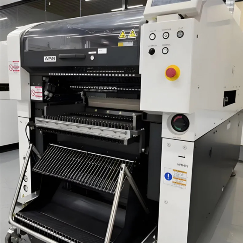
Evaluating advanced conveyor features requires looking at industry benchmarks. A Panasonic pick and place machine showcases how proprietary software and hardware ecosystems handle dimensional variability. Features like the NPM series' parallel processing capabilities allow for intelligent board routing. Different products run simultaneously on independent lanes, maximizing floor space and machine utilization.
Proprietary software ecosystems take dimensional data directly from the CAD file to automate the entire setup process. This includes calculating the exact rail width, determining the optimal acceleration profile based on the board's projected mass, and executing automated support pin placement. Integrating these parameters into the recipe file enables true zero-downtime changeovers. It removes the operator from the mechanical setup equation entirely, eliminating human error and ensuring the conveyor is perfectly configured for every production run.
Failing to adequately support a PCB carries severe financial consequences. When a board warps during placement, the Z-axis height changes unpredictably. Placement nozzles crash into the substrate, damaging expensive tooling and potentially cracking the board itself. Solder joints form unevenly, leading to hidden fractures during thermal cycling in the reflow oven. Poor support generates scrapped assemblies and costly rework. Mitigating this risk requires implementing strict setup verification protocols. You should utilize laser warpage measurement tools during the first article inspection. This confirms the board remains perfectly flat under simulated placement pressure before committing to a full production run.
Production managers constantly balance the time spent adjusting the line against the speed at which boards are processed. Stopping the line to manually adjust rails and reposition support pins destroys daily throughput. Investing in fully automated conveyor systems requires upfront capital but drastically reduces changeover bottlenecks. To optimize existing manual lines, planners group production runs by PCB width. Running all 150mm boards consecutively, regardless of the specific product, minimizes physical rail adjustments. This reclaims lost production hours and keeps the placement heads moving.
Deploying a dual-lane setup introduces the risk of mismatched cycle times. If lane one processes a simple, low-density board while lane two processes a complex, high-density board, the faster lane sits idle waiting for the slower lane to finish. This negates the throughput advantages of parallel processing. Utilizing advanced line-balancing software mitigates this bottleneck. The software optimizes placement head routing and provides independent lane control. Both lanes operate at maximum efficiency without forcing one to wait for the other, ensuring continuous board movement.
Oversized boards frequently push the limits of the camera's field of view. A standard vision system struggles to locate fiducials positioned at the extreme edges of a massive backplane. If the camera cannot establish a precise coordinate grid, placement accuracy degrades across the entire board. You must program multi-fiducial reading sequences. This forces the camera to read local fiducials near specific high-pin-count components rather than relying solely on global board fiducials. Verifying that the machine's X/Y gantry possesses the physical travel distance to cover the extended conveyor footprint is mandatory before accepting large-format jobs.
Conduct a comprehensive dimensional audit of your current and projected PCB portfolio, documenting maximum widths, lengths, and fully populated weights.
Calculate your average monthly changeover downtime specifically related to manual conveyor rail and support pin adjustments to justify automation investments.
Implement laser warpage measurement during first article inspections for any board exceeding 250mm in length or falling below 1.6mm in thickness.
Group your weekly production schedules by PCB width rather than product family to minimize physical line interventions.
Request physical board-handling demonstrations from equipment vendors using your heaviest, thinnest, and most challenging bare boards before finalizing any machinery purchase.
A: Standard machines typically handle boards down to 50mm x 50mm. Boards smaller than this lack the physical surface area to span the conveyor rails safely. To process micro-PCBs, engineers must use panelization, grouping multiple small boards into a larger, standardized array using V-scoring or routing tabs to prevent conveyor jamming and edge damage.
A: Preventing warpage requires active under-board support. Engineers use magnetic support pins, dedicated custom-machined blocks, or automated vacuum tooling placed beneath the center of the board. This tooling counteracts gravity and resists the downward Z-axis pressure applied by the placement heads, keeping the substrate perfectly flat.
A: Edge clearance is the mandatory keep-out zone along the parallel edges of the PCB, typically measuring 3mm to 5mm. This space allows the conveyor transport belts or chains to physically hold and move the board. No components, solder paste, or test points can be placed in this zone to avoid crushing.
A: While technically possible, high-speed machines are optimized for standard, rigid panels. Their internal architecture prioritizes rapid gantry movement over expansive conveyor space. Processing oversized boards often requires specialized modular extensions or shifting the production to a flexible placement machine designed specifically for large-format handling.
A: Dual-lane conveyors enable parallel processing. While the machine populates components on a board in lane one, a new board simultaneously indexes into position on lane two. This continuous cycle effectively eliminates the dead time usually spent waiting for a single board to enter and exit the placement zone.
A: Heavy boards generate significant momentum during transport. If a massive, fully populated board stops abruptly, inertia causes wet solder paste to smear and placed components to slide out of alignment. Engineers must program gradual, dampened deceleration profiles to bring heavy boards to a smooth, controlled stop.
A: Modern lines utilize SMEMA or Hermes communication protocols. When the placement machine automatically adjusts its internal conveyor width for a new product, it transmits a digital signal upstream to the screen printer and downstream to the reflow oven, commanding them to automatically adjust their rails to match.