Views: 0 Author: Site Editor Publish Time: 2026-08-08 Origin: Site
Approximately 60 to 70 percent of all Surface Mount Technology (SMT) defects originate in the solder paste printing process. Engineers optimize paste rheology, squeegee speed, and aperture design daily. Yet, stencil tension degradation remains a primary, often overlooked variable. As stencils undergo thousands of print cycles, continuous mechanical stress causes the metal foil to lose its initial tautness. This degradation fundamentally alters the separation dynamics between the stencil and the substrate.
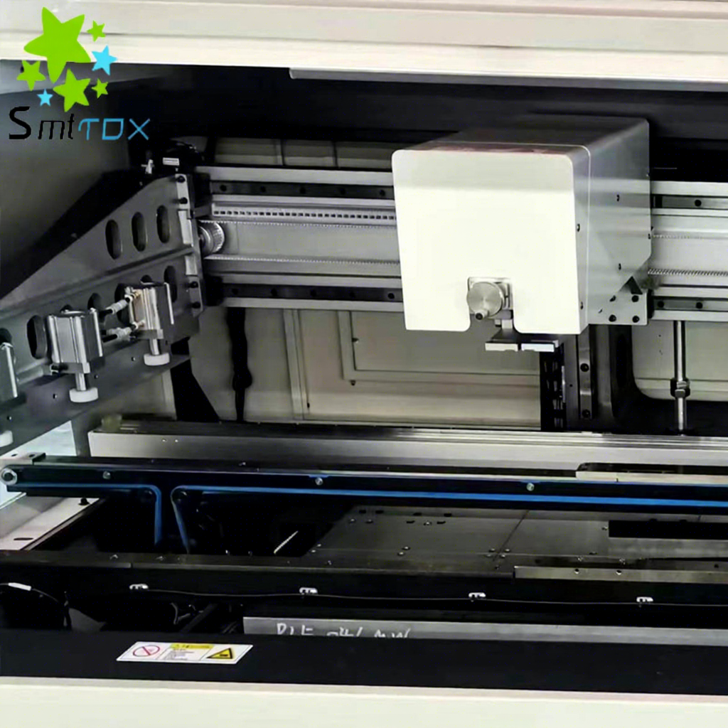
When stencil tension drops due to metal fatigue or improper mounting, manufacturers experience inconsistent paste release, damaged apertures, and immediate yield drops. A common floor-level reaction is increasing squeegee pressure to force the warped stencil flat against the board. This overcompensation accelerates stencil destruction, leading to coining and webbing breakage. The definitive engineering solution to manage these tension variables and eliminate costly manual workarounds is the selection and calibration of a high-grade PCB Printer Machine. Advanced printing platforms control pressure variables dynamically, ensuring consistent paste deposition even as stencil physical characteristics subtly shift over time.
Tension Dictates Paste Release: Optimal stencil tension ensures a clean "snap-off," preventing paste smearing and volumetric inconsistencies, particularly in fine-pitch components.
Pressure is Not a Substitute for Tension: Increasing squeegee pressure to fix tension loss causes irreversible stencil damage, including coining and rounded aperture edges.
Machine Capability Determines Yield: Modern automatic stencil printers utilize advanced clamping and closed-loop pressure feedback to mitigate the effects of minor tension variations.
Equipment ROI is Tied to Defect Reduction: Investing in highly capable printing equipment (such as a GKG PCB printer) directly reduces rework costs associated with bridging and insufficient solder.
Stencil tension is not a static property. From the moment a new stencil is mounted, it begins a gradual process of mechanical degradation. Repeated squeegee cycles apply downward and lateral forces across the foil. The highest stress concentrations occur near the frame border where the mesh interfaces with the solid metal. Over time, this continuous flexing causes plastic deformation in the stainless steel. The stencil loses its initial tautness, typically dropping from an optimal 35 to 40 N/cm to sub-30 N/cm levels. This localized sagging directly affects print consistency because the foil no longer sits perfectly parallel to the printed circuit board during the alignment phase.
We see this degradation happen in distinct phases on the production floor. First, the mesh adhesive stretches slightly during the initial 500 prints. Next, the stainless steel foil begins to yield under the repetitive downward force of the squeegee blades. Finally, localized sagging appears, usually near the center of the printable area where the squeegee stroke reaches maximum velocity. The type of frame used also dictates the rate of tension loss. Cast aluminum frames offer superior rigidity compared to hollow tubular frames. When a tubular frame is subjected to the high tension of a new stainless steel foil, the frame itself can bow inward slightly over time. This bowing relieves the tension on the mesh, causing the foil to sag even if the mesh adhesive remains intact. Engineers must specify high-rigidity frames for any stencil thinner than 4 mils to prevent this structural bowing.
The relationship between stencil tension, snap-off distance, and the area ratio dictates the volume of solder paste deposited on the pad. The area ratio is calculated by dividing the area of the aperture opening by the surface area of the aperture walls. A higher area ratio naturally results in greater solder deposition and less volumetric variation. This mathematical ideal only holds true if optimal tension facilitates the immediate, uniform separation of the stencil from the board.
If tension is low, the stencil peels away sluggishly. This delayed separation allows the paste to cling to the aperture walls rather than releasing cleanly onto the pad, destroying the benefits of a well-designed area ratio. For example, when printing 0201 imperial components, the aperture walls are incredibly close together. A sluggish snap-off caused by a loose stencil will pull the paste right back out of the cavity, leaving an insufficient deposit that will fail optical inspection.
Stencil thickness heavily influences how the metal responds to tension variations. Modern electronics manufacturing requires thinner stencils—often 3 to 4 mils—to accommodate fine-pitch components like 0.3mm micro-BGAs and 01005 passives. These thinner foils are significantly more susceptible to tension-related warping. A thick stencil possesses inherent structural rigidity that masks minor tension drops. A thin stencil relies entirely on the mesh tension to remain flat.
When tension degrades on a thin stencil, the foil ripples under the squeegee blade. This requires tighter machine controls to prevent insufficient solder deposits and maintain strict coplanarity between the squeegee blade, the foil, and the substrate. Stepped stencils, which feature varying thicknesses across the same foil, are even more vulnerable. The step-down areas create natural weak points where tension loss manifests as severe localized warping.
Tension loss disproportionately impacts apertures based on their orientation relative to the squeegee stroke. Apertures oriented parallel to the direction of the squeegee travel are highly vulnerable to paste scooping. When the foil lacks tension, the squeegee blade dips slightly into the parallel aperture, scooping out paste and causing volumetric variations.
Conversely, apertures oriented perpendicular to the stroke allow the squeegee to glide over the narrow opening, rolling the paste into the cavity without dipping. Maintaining high stencil tension prevents the foil from deflecting downward under the blade, ensuring consistent volume regardless of how the apertures are laid out on the board. Using a 60-degree squeegee angle instead of a 45-degree angle can reduce the downward deflection, but it cannot fix a stencil that has fundamentally lost its structural tautness.
Inadequate tension prevents the stencil from peeling away cleanly during the separation phase. Instead of a sharp, vertical snap-off, the loose foil drags against the deposited paste. This dragging motion causes paste to smear on the underside of the stencil. Once the underside is contaminated, subsequent prints will suffer from poor deposition and incomplete transfer to the PCB pads.
Operators will notice "dog-ear" formations on the solder deposits or ragged edges that fail to match the pad geometry. This smearing directly correlates to a lack of mechanical energy in the foil necessary to break the surface tension of the solder paste. You will often see this defect cluster around the center of the board, where the foil sag is most pronounced.
A successful print requires a tight "gasket" seal between the bottom of the stencil and the top of the PCB pad. Tension loss prevents this seal. When the foil sags, microscopic gaps form between the stencil and the board. During the print stroke, the hydraulic pressure of the rolling solder paste forces flux and metal particles through these gaps.
This irregular sealing allows paste to bleed under the stencil. As the paste spreads outward from the pad area, it bridges the gap to adjacent pads. During the reflow process, this bridged paste coalesces into solid electrical shorts, requiring immediate manual rework. The fluid dynamics of the flux mean that even a 10-micron gap caused by a loose stencil is enough to cause a catastrophic bleed-out on a 0.4mm pitch QFP. The viscosity of the solder paste plays a role here as well. A lower viscosity paste, often used for high-speed printing, will bleed through a compromised gasket seal much faster than a high-viscosity paste. When tension drops, the machine operator might try to switch to a thicker paste to stop the bleeding. This is a flawed workaround. Thicker paste requires a cleaner snap-off to release from the apertures. Since the loose stencil already suffers from a sluggish snap-off, the thicker paste will simply clog the apertures, trading a bridging defect for an insufficient solder defect.
When operators encounter a warped or low-tension stencil, the most common reaction is to increase the squeegee pressure. The logic assumes that more downward force will push the warped foil flat against the board. This overcompensation creates severe mechanical damage. Excessive pressure forces the stencil to bend sharply around the edges of the PCB and the tooling pins, leading to coining—a permanent deformation of the foil.
The immense downward force crushes the delicate metal webbing between fine-pitch apertures. The aperture edges become rounded, destroying the gasket seal permanently and guaranteeing bleed-out on every subsequent print. Once a stencil is coined, no amount of machine calibration can save it. It must be scrapped and replaced.
Defect Type | Visual Indicator | Root Cause Related to Tension | Immediate Corrective Action |
|---|---|---|---|
Smearing | Paste on the underside of the stencil; ragged deposit edges. | Low tension causing sluggish snap-off and dragging. | Run a vacuum wipe cycle; verify tension with a meter. |
Bridging | Paste connecting two adjacent pads. | Poor gasketing due to foil sag; paste bleeds under the stencil. | Check board support pins; replace fatigued stencil. |
Coining | Permanent indentation in the foil around tooling pins. | Operator overcompensation with excessive squeegee pressure. | Scrap the stencil; recalibrate squeegee pressure limits. |
Scooping | Concave paste deposits in parallel apertures. | Foil deflecting downward into the aperture under the blade. | Increase tension; switch to a 60-degree squeegee angle. |
A successful printing operation is defined by zero-defect paste deposition at high throughput without premature stencil degradation. Achieving this requires hardware that actively manages the physical realities of the stencil. The machine must hold the frame rigidly, apply exact and repeatable downward force, and separate the board from the foil with micron-level precision. Evaluating equipment based on these success criteria shifts the focus from basic alignment capabilities to advanced material handling and dynamic pressure control.
The architecture used to secure the stencil frame directly impacts tension uniformity. Basic printers use simple Y-axis clamps that push the frame against a hard stop. This method often distorts the frame, creating uneven tension across the printable area. High-end platforms utilize rigid, four-sided pneumatic or motorized clamping systems.
By securing the frame from all directions, the machine maintains uniform tension across the entire foil. This stability prevents the stencil from shifting microscopically during the squeegee stroke, ensuring that the gasket seal remains intact even at high print speeds. Top-clamping mechanisms that pull the frame flat against the machine rails offer superior stability compared to older side-clamping designs.
Managing tension variations requires programmable squeegee pressure with real-time feedback. Advanced machines utilize load cells mounted on the squeegee head to monitor the exact downward force applied to the foil. If the machine detects resistance variations, it adjusts the pressure dynamically.
This closed-loop system must be paired with precise squeegee speed controls. Balancing speed and pressure prevents the smearing versus coining dilemma. The machine applies just enough force to achieve a clean wipe across the foil without over-stressing the metal, extending the lifespan of the stencil while maintaining print quality. Metal squeegee blades require tighter pressure control than polyurethane blades because they do not flex to absorb localized tension drops.
Catching tension-related defects before the board reaches the pick-and-place machine is critical for maintaining line yield. Modern equipment features integrated 2D or 3D Automated Stencil Inspection (ASI) capabilities. These camera systems scan the foil after the print stroke to detect aperture blockages, rounded edges, and tension-related smearing on the underside of the stencil.
By identifying these issues immediately, the machine can trigger an automated cleaning cycle or alert the operator to replace a fatigued stencil before a batch of defective boards moves down the line. 3D ASI provides volumetric data, allowing engineers to see exactly how much paste is left inside the aperture due to a sluggish snap-off. Advanced ASI systems use structured light or laser triangulation to measure the exact height of the paste left on the stencil underside. If the system detects a paste height exceeding a programmable threshold—typically 15 to 20 microns—it automatically halts the printer and initiates a wet wipe cycle. This closed-loop communication between the inspection camera and the wiper mechanism is the only reliable way to manage the unpredictable nature of tension degradation during a continuous production run.
Machine Feature | Functionality | Impact on Stencil Tension & Defect Mitigation |
|---|---|---|
Four-Sided Pneumatic Clamping | Secures the stencil frame rigidly from all directions. | Prevents frame distortion and maintains uniform foil tension across the entire printable area. |
Closed-Loop Pressure Feedback | Uses load cells to adjust squeegee downward force in real-time. | Eliminates coining and webbing breakage by preventing operator overcompensation. |
Programmable Separation Speed | Controls the exact velocity of the board dropping away from the stencil. | Optimizes the snap-off dynamic, preventing paste smearing and ensuring clean aperture release. |
Automated Stencil Inspection (ASI) | Scans apertures for blockages and underside smearing. | Detects early signs of tension loss and triggers cleaning cycles before bridging occurs. |
When tension drops and boards start failing inspection, operators often resort to DIY workarounds. A common manual fix involves taping the board to the back of the stencil after alignment to force a gasket seal. Operators apply pressure manually, swipe the paste, and peel the tape away. These methods are fundamentally unscalable and introduce severe alignment errors.
Manual interventions cannot replicate the micron-level precision required for modern SMT layouts. Manual fixes apply uneven pressure, which exacerbates metal fatigue and guarantees that the stencil will fail completely within a few production runs. Shimming the frame with cardboard or tape to artificially boost tension only warps the frame further, destroying the coplanarity of the entire setup.
Contrasting manual interventions with the capabilities of an automatic stencil printer reveals a massive gap in process control. Automated platforms handle minor tension variations through precise parameter adjustments rather than brute force. One of the most critical automated features is the under-stencil cleaning system.
When tension drops slightly and underside bleeding occurs, the machine executes programmable dry, wet, and vacuum wiping cycles. The vacuum function pulls trapped paste out of the apertures, restoring the print quality without requiring the operator to stop the line and scrub the foil manually. High-end printers allow engineers to program specific solvent dispensing rates to match the exact tackiness of the solder paste being used.
High-reliability manufacturing sectors, such as automotive and aerospace, require strict adherence to IPC standards. Manual tension compensation destroys process traceability. Automated parameter control ensures that every variable—from squeegee pressure to separation speed—is logged and verified against the product recipe.
If a defect occurs, engineers can review the machine data to determine if a tension drop or a pressure anomaly caused the issue. This level of traceability is mandatory for compliance and cannot be guaranteed when operators are manually tweaking the process to force a failing stencil to work.
Evaluating a printer requires matching its technical specifications to the realities of your board designs. Fine-pitch components demand exceptional alignment accuracy, typically ±12.5 microns at 6 sigma. This accuracy is useless if the machine cannot handle the high-tension, electroformed, or nano-coated stencils required for these layouts.
The equipment must feature robust tooling options, including dedicated vacuum blocks and support pins, to hold the substrate perfectly flat against the high-tension foil. Without adequate board support, the tension of the stencil will bow the PCB, destroying the gasket seal. A high-quality pcb printer machine will offer programmable tooling pin placement to ensure the board is supported exactly where the squeegee applies the most pressure.
When upgrading your line, evaluating industry-standard platforms provides a baseline for required features. Testing a GKG PCB printer allows engineers to assess specific tension-handling capabilities. Focus on the squeegee head design. Does it utilize independent motor control for the front and rear blades?
Review the software interface. Can engineers program multi-stage separation speeds to optimize the snap-off for challenging area ratios? The platform must offer granular control over the physical forces applied to the stencil to maximize yield. Look for systems that allow you to decouple the squeegee downward stroke from the horizontal travel speed.
The material of the squeegee blade interacts directly with the tension of the stencil. Polyurethane blades offer flexibility, which can sometimes mask minor tension inconsistencies by conforming slightly to the warped foil. However, this flexibility often leads to paste scooping in larger apertures. Metal blades, typically made of stainless steel or electroformed nickel, provide a rigid wiping edge. Metal blades require a perfectly tensioned stencil to function correctly. If a metal blade is used on a sagging stencil, the rigid edge will catch on the warped areas, causing severe coining and potentially ripping the mesh. Selecting the right blade material requires a thorough understanding of your baseline stencil tension and the specific area ratios of your board design.
The financial justification for premium printing equipment relies entirely on yield improvements. Scrapped boards, frequent stencil replacements, and extensive manual rework drain profitability. A machine equipped with closed-loop pressure control and automated cleaning directly targets the root causes of bridging and insufficient solder.
By extending the usable life of stencils and preventing tension-related defects from reaching the reflow oven, manufacturers drastically reduce their scrap rates. The focus must remain on the equipment's ability to maintain a zero-defect output over high-volume production runs.
Protecting your equipment investment and maintaining print quality requires strict operational procedures. Proper maintenance ensures the printer operates with optimal materials. Implement the following protocols on the factory floor:
Audit stencil tension regularly using a calibrated tension meter, taking measurements at the center and all four corners.
Document the baseline tension upon receipt and track the degradation over time in your manufacturing execution system.
Store stencils vertically in dedicated racks to prevent physical damage to the mesh and foil.
Establish rigorous ultrasonic cleaning cycles to remove hardened flux and paste from the apertures without applying mechanical stress to the foil.
Inspect the squeegee blades weekly for nicks or wear that could cause uneven pressure distribution across the stencil surface.
Stencil tension is a foundational variable in SMT yield. Attempting to manage metal fatigue, warping, and tension degradation without precise, automated equipment leads to compounding defect rates. Smearing, bridging, and coining are direct results of poor tension management and operator overcompensation. Securing a reliable printing process requires hardware capable of adapting to the physical realities of the stencil through dynamic pressure control and rigid clamping.
When shortlisting equipment, demand specific mechanical features. Rigid four-sided frame clamping, closed-loop pressure and speed control, and integrated automated inspection are non-negotiable for high-yield environments. These features protect the stencil from mechanical damage while ensuring consistent paste deposition across fine-pitch layouts.
To optimize your printing process, take the following next steps:
Audit your current solder paste defect logs, specifically categorizing instances of smearing and bridging to identify potential tension failures.
Procure a calibrated tension meter and measure your existing stencils to establish a baseline degradation rate for your production environment.
Review your squeegee pressure settings and eliminate any manual overrides that exceed the recommended kg/cm limits for your blade length.
Schedule technical demonstrations with equipment vendors to test their fine-pitch capabilities using your most challenging board designs.
A: Stencil tension should be checked using a calibrated tension meter every 10,000 print cycles or at the beginning of each major production shift. Regular auditing catches metal fatigue early, allowing engineers to replace degrading stencils before tension drops cause smearing and bridging defects on the production line.
A: Ideal pressure is relative to the squeegee length, typically ranging from 0.15 to 0.3 kg per centimeter of the squeegee blade. This pressure must be optimized alongside print speed to achieve a clean wipe across the foil without coining the metal or damaging the stencil webbing.
A: Advanced clamping mechanisms and vacuum tooling can mitigate minor warping and improve the gasket seal. Severe tension loss or permanent coining cannot be fixed by the machine. Overcompensating with higher pressure will only cause bridging. Severe warping requires immediate stencil replacement.
A: Thinner stencils require higher, more uniform tension to maintain structural integrity and prevent warping during the snap-off phase. According to the area ratio rule, thinner foils improve paste release for fine-pitch components, but only if the tension is sufficient to pull the foil away instantly and uniformly.
A: Visible indicators of metal fatigue include rounded aperture edges, visible stress fractures near the frame border, localized sagging or rippling of the foil, and a failure to lay flat against the substrate. These physical deformations guarantee inconsistent solder paste volumes.
A: Smearing is typically caused by insufficient stencil tension, which prevents a clean snap-off. It is also caused by poor gasketing against the PCB, allowing paste to bleed outward, or an inadequate under-stencil cleaning frequency that fails to remove accumulated flux and metal particles.