Views: 0 Author: Site Editor Publish Time: 2026-10-12 Origin: Site
In the highly demanding realm of Surface Mount Technology, frontline data reveals a stark reality. Up to 70 percent of all printed circuit board assembly defects trace their origins back to the solder paste printing process. Even microscopic deviations in print alignment initiate a cascading effect. This leads to bridging, insufficient solder coverage, or tombstoning during the reflow phase. Modern smart factories rely heavily on advanced solder paste inspection systems to combat these issues. However, merely detecting a flawed print after the fact fails to meet high-yield manufacturing demands.
This operational gap is exactly where the closed-loop system steps in. It serves as a transformative technological bridge. This architecture allows inspection equipment to communicate directly with the stencil printer. It identifies, calculates, and automatically corrects printing offsets in real-time. Let us break down the intricate mechanics behind this automated feedback loop. We will explore how offset correction functions on the factory floor and why upgrading is an indispensable strategy for maximizing production yield.
Key Takeaways
Proactive Defect Prevention: Shifts production from merely flagging errors to actively preventing them through on-the-fly printer adjustments.
Real-Time Data Communication: Leverages machine-to-machine protocols to transmit precise X, Y, and Theta offset coordinates directly to the upstream stencil printer.
Automatic Offset Correction: The printer physically micro-adjusts the stencil alignment or squeegee parameters prior to processing the subsequent board.
3D Precision is Mandatory: True closed-loop control necessitates three-dimensional inspection capabilities to accurately quantify volume, height, and area.
High ROI: Deploying top-tier inspection equipment drastically curtils rework expenditures and minimizes scrap rates.
Historically, manufacturers relied on traditional 2D inspection methods. These evaluated only the surface area of the deposited paste. Legacy systems functioned much like a flat photograph. They were easily deceived by lighting conditions and incapable of assessing depth. In contrast, the transition to 3D solder paste inspection revolutionized our industry. Modern optical systems capture a comprehensive topographical map. They accurately measure volume, height, area, and shape. Volume remains the absolute most critical metric for forging robust electrical joints. Without accurate volumetric data, any attempt at automated process correction is inherently flawed.
On a bustling factory floor, the inspection machine is strategically stationed directly downstream from the stencil printer. Its primary mandate is intercepting printing anomalies before expensive components are placed. Catching these deviations early saves an exponential amount of capital. It prevents complex post-reflow rework and keeps the assembly line moving seamlessly.
Offsets do not occur in a vacuum. They are the byproduct of dynamic production environments. Mechanical components experience minute wear and tear throughout a standard shift. Stencil tension may gradually loosen. The squeegee blade might degrade and warp slightly under continuous pressure. Furthermore, environmental fluctuations play a massive role. A sudden spike in factory temperature or a drop in humidity alters paste rheology. This causes it to slump or pull unevenly during the stencil separation phase. Even bare boards themselves exhibit slight warpage or dimensional stretching from batch to batch.
Think about the traditional manual correction process. When a quality engineer noticed a trend of misaligned prints, the protocol was highly disruptive. Operators had to physically halt the production line. They opened the printer, manually wiped the stencil, and keyed in estimated coordinate tweaks based on visual guesswork. This manual intervention is notoriously slow and heavily prone to human error. By the time an operator intervenes, several defective boards have already passed down the line.
A closed-loop system represents a continuous, self-regulating cycle of execution and refinement. It consists of four distinct phases. First is execution, meaning the initial paste printing. Next is measurement via high-speed optical scanning. Third is analysis to calculate the exact deviation from the ideal baseline. Finally, feedback transmits actionable adjustment commands back to the printer. The machines function as a synchronized unit rather than operating in isolated silos.
For this architecture to function flawlessly, the inspection hardware must speak the exact same digital language as the printing hardware. A 3D online SPI machine utilizes industry-standard communication protocols, most notably IPC-HERMES-9852 and IPC-CFX. These standardized frameworks allow machines from entirely different manufacturers to swap complex datasets in milliseconds. Proprietary software barriers no longer impede factory automation.
The correction process begins the moment a freshly printed board glides into the inspection chamber. Advanced phase-shift moiré technology or dual-projection laser profiling captures a high-resolution topographical map. This scan executes in a fraction of a second.
Crucially, intelligent closed-loop algorithms do not panic and react to a single random anomaly. Instead, the software meticulously searches for statistical trends. Looking at broader manufacturing trends across the industry, the shift towards extreme miniaturization has made automated offset correction a fundamental operational requirement. Metric components like 01005 and 0201 demand absolute precision. Industry analysts and process engineers note that closed-loop architectures are rapidly evolving from simple pass or fail gateways into predictive control hubs. Current industry consensus highlights that modern algorithms analyze statistical drift across multiple consecutive prints. By charting these micro-trends dynamically, the system adjusts the printer alignment before the drift crosses the threshold into an actual defect. This effectively creates a zero-defect manufacturing environment.
Upon identifying a legitimate trend, the system calculates the precise counter-adjustment required. For instance, if three consecutive boards exhibit a positive 0.02mm drift along the X-axis, it formulates a specific data packet. This packet details the necessary X-axis shift, Y-axis shift, and Theta rotational angle compensation. This correction data routes instantaneously back to the stencil printer. Receiving the command, the printer utilizes its internal motorized vision alignment system. It physically manipulates the stencil frame or the clamping table. The motors execute micro-movements, shifting the alignment by the exact specified microns before the squeegee blade initiates the next print stroke.
Upgrading to a closed-loop system requires matching specific hardware capabilities to your production needs. You cannot simply plug in any standard machine and expect autonomous offset correction. When evaluating a Kohyoung SPI machine or similar top-tier equipment, engineers must look for concrete parameter benchmarks.
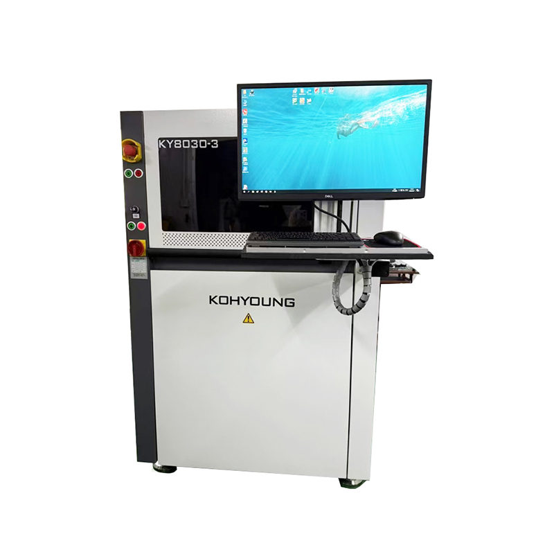
First, inspect the camera resolution and projection technology. A true closed-loop setup requires dual-projection technology to eliminate shadow effects on densely populated boards. For example, systems like the Koh Young KY8030-3 utilize full 3D shadow-free measurement with options for 10-micron or 15-micron resolution. This granular detail is non-negotiable for ultra-small component pads.
Specifically, you must consider the camera sensor capability. High-end alternatives like the Mirtec MS-11 leverage a 15 Megapixel or even 25 Megapixel CoaXPress camera system combined with precision telecentric lenses. This ensures the volumetric data fed back to the printer is mathematically flawless.
Feature Requirement | Minimum Standard for Closed-Loop | Industry Leading Benchmark |
|---|---|---|
Measurement Technology | 3D Phase Shift Profilometry | True 3D Dual Projection without shadow blind spots |
Camera Resolution | 15 microns | 10 microns or 15 to 25 Megapixel CoaXPress |
Communication Protocol | Basic SECS or GEM | Native IPC-CFX and Hermes 9852 |
Trend Analysis | Simple threshold triggers | AI-driven predictive statistical process control |
The intelligence of a closed-loop setup extends far beyond simple X and Y alignment. Advanced inspection systems easily detect the telltale signs of clogged stencil apertures or paste smearing on the underside of the foil. When the software recognizes that volume is degrading inconsistently due to blockages, it takes a different action. Rather than sending an alignment offset, it transmits a direct command to the printer to initiate an automatic under-stencil wipe sequence.
In addition, optical sensors might detect a uniform lack of solder paste volume across the entire board despite perfect alignment. The system understands that the issue lies in the application mechanics. In response, advanced configurations suggest or automatically implement adjustments to the squeegee downward pressure or the print stroke speed. This forces the optimal amount of paste through the apertures.
The financial justification for implementing this technology is heavily anchored in the well-known Rule of 10 in electronics manufacturing. This principle states that the cost to identify and fix a defect increases tenfold at each subsequent stage of assembly. Catching and automatically correcting errors right at the printer stage prevents defects from reaching the reflow oven. Facilities save immense capital that would otherwise be burned on manual rework and scrapped assemblies.
Furthermore, closed-loop systems dramatically boost overall line utilization. Entirely eliminating the need for operators to halt production for manual printer adjustments keeps the line running continuously. Consequently, valuable skilled labor is reallocated from passively monitoring printers to executing higher-value engineering tasks.
The journey of a printed circuit board through a closed-loop inspection system represents the pinnacle of modern manufacturing automation. Component sizes continue to shrink to near-microscopic dimensions. Relying on manual offset correction is no longer a viable operational strategy. Investing in robust, high-precision inspection equipment equipped with automated closed-loop feedback is the definitive path to achieving a zero-defect smart factory.
Production managers and process engineers must evaluate their current communication capabilities and embrace the predictive power of automated alignment correction. If you are looking to upgrade your assembly line with industry-leading technology, we highly recommend exploring the comprehensive range of solutions available. You can find the exact brand and product parameters to match your specific factory requirements at https://www.smtwenzhan.com. Upgrading today ensures your production line remains competitive, efficient, and defect-free.
No. For the closed-loop architecture to function, the stencil printer must be explicitly equipped with motorized alignment capabilities and compatible software. It requires the ability to support external machine-to-machine communication protocols to actively receive, parse, and execute incoming offset data.
The primary distinction lies in spatial measurement. 2D inspection only evaluates the surface area along the X and Y axes of the paste deposit. In contrast, 3D inspection introduces the Z-axis for height into the equation. This addition allows for highly accurate volumetric measurement, which is the absolute most critical factor in preventing weak or defective solder joints.
The inspection software relies on highly specific geometric algorithms to differentiate between root causes. If the entire print deposit is uniformly shifted in one specific direction, the system triggers an offset correction. However, if the volume is degrading inconsistently across the board, or if specific shape defects begin to appear, the software interprets this as a clogged or dirty stencil. It then triggers a cleaning cycle instead.
No, it does not. A modern inspection machine is equipped with immense processing power, capable of analyzing complex topographical data in mere milliseconds. The feedback data is calculated, transmitted, and executed by the printer concurrently with the standard board transfer process. This results in zero negative impact on the overall production cycle time.
Ultra-miniature metric components have virtually zero tolerance for solder volume variations or placement offsets. A manual operator simply cannot see or accurately adjust for deviations measured in single-digit microns. A closed-loop system uses high-resolution cameras and automated algorithms to guarantee the microscopic precision required for these advanced packages.
Top-tier systems process the full 3D scan, compare it against the Gerber file, calculate statistical trends, and transmit the offset correction data in a fraction of a second. This entire computational feedback loop happens seamlessly between the time one board leaves the printer and the next board enters it.