Views: 0 Author: Site Editor Publish Time: 2026-09-15 Origin: Site
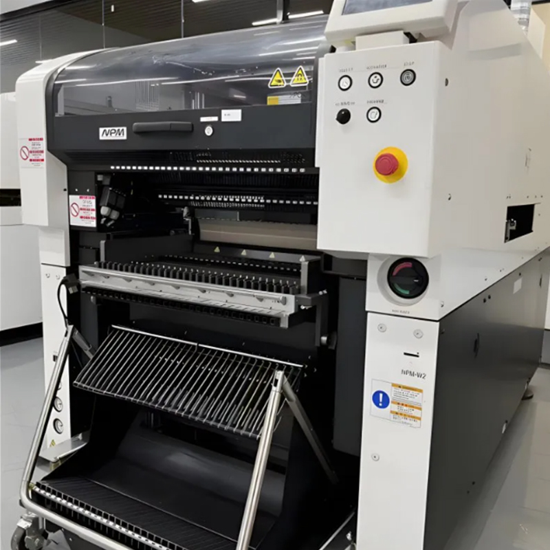
Modern PCB assemblies increasingly combine ultra-miniature passives with tall, odd-form components, creating significant Z-axis challenges during surface mount assembly. Misconfigured placement settings for varying component heights result in cracked components, displaced solder paste, tombstoning, and compromised coplanarity. These defects directly impact first-pass yield and drive up rework rates on the production floor. Establishing strict protocols for Z-axis stroke, placement pressure, and vision recognition depth solves this mechanical challenge. The physical distance the nozzle travels must adapt instantly between a 0.2mm high chip and a 15mm high capacitor. From translating CAD data into machine libraries to utilizing dynamic sensor feedback, this guide details how to evaluate and configure these settings. We will show you how to optimize a Pick And Place Machine to handle extreme height variances without degrading overall line throughput.
Z-Axis Precision Dictates Yield: Accurate placement stroke and controlled overdrive are required to seat tall components securely without crushing low-profile passives.
Data Translation is Foundational: Flawless placement begins in PCB design software; accurate component dimensions and base points must be correctly exported to the machine's component library.
Throughput Trade-offs: Accommodating high height variances often requires a flexible SMT placement machine, which may operate at lower CPH (Components Per Hour) than dedicated chip shooters due to extended Z-axis travel times.
Vision System Dependency: Component height changes necessitate dynamic focal adjustments in the machine's upward-looking and on-the-fly vision systems to ensure accurate X-Y centering.
Hardware Mitigation: Utilizing compliant nozzles and programmable placement force sensors minimizes the risk of substrate deflection and component damage during high-mix runs.
Achieving zero-defect placement across a single board containing drastic height differences requires absolute mechanical synchronization. A standard production run frequently features 0.2mm high 01005 passives placed millimeters away from 15mm high electrolytic capacitors or bulky connectors. Success means the placement head descends just enough to bed the component into the solder paste without applying excessive force. If the stroke is too shallow, the part drops from the nozzle and shifts off the pads. If the stroke is too deep, the nozzle crushes the component body or splatters the wet solder paste across adjacent traces, causing shorts. Controlling this vertical travel requires real-time communication between the component library data and the mechanical Z-axis servo motors on the placement head.
Mechanical precision relies entirely on accurate digital instructions. Centroid files generated from PCB design software, such as Altium Designer or Mentor Graphics, provide the foundational X, Y, rotation, and Z dimensions. The Z-axis data dictates the physical height of the component body. When process engineers import this data, they must establish the correct base point and Z-offset in the machine's component library. The operating system uses these figures to calculate the exact distance from the nozzle tip to the bare PCB surface. If a 10mm component is mistakenly entered as 2mm in the library, the machine will attempt to drive the nozzle 8mm into the FR4 substrate. Verifying package dimensions against physical digital caliper measurements before running a new batch prevents catastrophic head crashes and spindle damage.
The Z-axis travel path begins at a safe clearance height above the tallest component on the board and ends at the PCB surface. The machine calculates the descent based on programmed board thickness and component height. Stopping exactly at the surface is rarely sufficient for a reliable solder joint. Engineers utilize a setting called overdrive. Overdrive is the slight additional downward travel programmed after the component makes initial contact with the board. This extra fraction of a millimeter ensures the component leads bed properly into the wet solder paste. Proper overdrive prevents parts from floating or skewing during the reflow oven process. Setting overdrive requires balancing the need for paste adhesion against the risk of paste displacement. A flat leadless package like a QFN might require only 0.05mm of overdrive, while a J-lead component might need 0.15mm to ensure all pins make contact.
Downward travel distance is only half of the mechanical equation; the force applied during that travel dictates the physical stress on the assembly. Modern equipment utilizes programmable force control to manage placement pressure dynamically. Brittle components, such as ceramic capacitors, are highly susceptible to micro-cracking if struck with too much force. For these parts, the machine must decelerate smoothly and apply minimal pressure, typically measured in Newtons (N). Conversely, heavy, tall connectors often feature multiple pins that must push through dense solder paste or into through-holes for pin-in-paste applications. These heavy components require a higher programmable force to ensure they seat flush against the substrate. Independent piezoelectric force sensors on the placement spindles allow the machine to adjust pressure on the fly for each specific package type.
Accurate X-Y centering depends on the machine's vision system capturing a clear image of the component leads or bumps. Standard optical centering systems have severe depth of field limitations. A camera focused perfectly for a flat 0402 chip will capture a blurry, unusable image of the leads on a 15mm tall connector. Component height changes necessitate dynamic focal length adjustments. Advanced placement heads use multi-tier lighting and dynamic focus lenses to accurately image tall components. The upward-looking camera must shift its focal plane instantly as the head passes over it. Without this dynamic adjustment, the vision software cannot accurately calculate the center point or detect bent leads on tall, odd-form packages.
Component Type | Typical Height Range | Recommended Overdrive | Placement Force Target | Vision Lighting Requirement |
|---|---|---|---|---|
Micro Passives (01005, 0201) | 0.15mm - 0.30mm | 0.05mm - 0.10mm | 1.0N - 2.5N | Standard Coaxial |
Standard ICs (QFN, SOIC) | 0.80mm - 2.50mm | 0.10mm - 0.15mm | 3.0N - 5.0N | Multi-angle Ring Light |
Electrolytic Capacitors | 5.00mm - 12.00mm | 0.15mm - 0.20mm | 5.0N - 8.0N | Dynamic Focus / Side Light |
Heavy Connectors | 10.00mm - 25.00mm | 0.20mm - 0.30mm | 10.0N - 25.0N | Dynamic Focus / High Angle |
Low-profile passives make up the vast majority of placements on a standard PCB. The configuration strategy here prioritizes speed and minimal impact. Settings dictate a high-speed Z-axis descent to maximize cycle time. The deceleration curve is steep, and overdrive is kept minimal, typically between 0.1mm and 0.2mm. Placement force is restricted to a low threshold, generally between 1.5N and 3N. This configuration maximizes throughput on a high speed SMT placement machine. The minimal force and shallow overdrive prevent solder paste splatter, ensuring that tightly spaced 0201 pads do not bridge during reflow. Maintaining these strict limits preserves both component integrity and placement speed across thousands of cycles per hour.
Components in the medium-to-tall category require a different mechanical approach. Electrolytic capacitors and large wire-wound inductors carry more mass and have higher centers of gravity. The settings must utilize a slower Z-axis deceleration profile. If the head descends too rapidly and stops abruptly, the momentum can cause the heavy component to shift on the nozzle tip before placement. Engineers program an increased placement force to overcome the component weight and any resistance from the solder paste. This increased pressure prevents the component from shifting during board indexing as the conveyor moves the PCB to the next station. Proper seating ensures the heavy part remains stable until the solder melts and solidifies in the oven.
Odd-form components and extreme height connectors introduce the highest level of complexity. Settings demand the maximum Z-axis clearance configuration to avoid clipping previously placed parts. These components often require specialized gripper nozzles rather than standard vacuum tips. The placement stroke is typically multi-stage. The head descends rapidly to a safe clearance plane, then moves slowly for the final placement to ensure pins align perfectly with the pads or holes. Utilizing dynamic sizing and positioning settings within the machine software allows the system to auto-change placement parameters. When nested or stepped components alter the effective placement height, the software recalculates the stroke dynamically. This prevents collisions and accommodates non-standard center-of-gravity issues common in bulky connectors.
Measure the physical component body height and lead length using digital calipers to establish a baseline.
Input the exact dimensions into the machine's component library, ensuring the Z-offset accounts for the seating plane.
Select a nozzle or gripper designed specifically for the component's mass and surface area.
Program a multi-stage Z-axis descent profile: fast approach to clearance height, slow search to contact, and controlled overdrive.
Run a dry test without solder paste to verify clearance over adjacent components and confirm the nozzle releases the part without sticking.
Execute a wet test with solder paste and inspect the displacement under a microscope to finalize the force settings.
Standard chip shooters are engineered for maximum X-Y speed. They utilize lightweight rotary heads or multi-spindle configurations designed to place tens of thousands of components per hour. This speed comes at the cost of Z-axis flexibility. These machines are typically restricted to components under 3mm to 5mm in height. Their Z-axis stroke is physically short to minimize travel time. Forcing high-speed machines to handle tall components introduces severe risks. The limited clearance causes head collisions with previously placed tall parts. The rapid acceleration and deceleration profiles cause heavy components to drop from the vacuum nozzles mid-flight, leading to scrap and machine jams.
When a bill of materials includes extreme height variances, production lines must integrate specialized equipment. A flexible SMT placement machine provides the necessary mechanical range. Key features include an extended Z-axis stroke, often capable of handling components 25mm or taller. These machines feature independent Z-servo control per spindle, allowing precise, customized descent profiles for each nozzle. They incorporate dynamic force feedback, adjusting pressure instantly based on resistance. While they operate at lower theoretical speeds than chip shooters, their flexibility is vital for overall line balancing. They manage the bottleneck of odd-form placement, allowing the high-speed machines upstream to focus exclusively on rapid passive placement.
Equipment manufacturers tackle extreme height variances using proprietary hardware and software combinations. Analyzing these approaches helps engineers optimize their specific lines. A Panasonic pick and place machine utilizes advanced head configurations combined with auto-teaching software. The system dynamically adjusts height parameters by learning the physical characteristics of the component during the first few placements. Advanced software-driven height mapping is becoming an industry standard. Machines use laser sensors to map the bare board before placement begins. The board warpage compensation algorithms auto-change Z-heights in real-time. If the center of the PCB bows upward by 0.5mm, the software automatically shortens the Z-stroke for components in that specific zone, ensuring consistent placement pressure across the entire warped substrate.
Physics dictates that longer travel distances require more time. Taller components require the placement head to retract higher to clear the board safely before moving to the next coordinate. This increased Z-axis travel time directly reduces the cycle rate. When mixing extreme heights on a single gantry, the machine defaults to a safe clearance height that accommodates the tallest part on the board. If a 15mm capacitor is placed early in the cycle, the head must retract at least 16mm for every subsequent placement to avoid collisions. Calculating the true impact on CPH requires analyzing the placement sequence. Grouping tall components at the end of the placement program mitigates this cycle time reduction, allowing the machine to operate with a lower clearance height for the majority of the run.
Engineers constantly balance placement speed with impact force. Running a machine at maximum Z-axis velocity increases the kinetic energy transferred to the component and the board upon impact. This energy causes solder paste splatter, which leads to solder balls and short circuits during reflow. It risks micro-cracking in sensitive components. Slowing the Z-axis descent mitigates these risks but reduces throughput. The decision comes down to yield economics. The cost of false failures, manual rework, and scrapped assemblies far outweighs the cost of slightly reduced machine cycle times. Process engineers conduct trial runs to find the optimal velocity that guarantees zero splatter and zero cracking while maintaining acceptable production schedules.
Observed Defect | Z-Axis Root Cause | Corrective Action |
|---|---|---|
Solder Paste Splatter | Excessive placement force or velocity. | Reduce Z-axis descent speed; lower force limit by 1N-2N. |
Component Floating / Skewing | Insufficient overdrive. | Increase overdrive by 0.05mm increments until seated. |
Cracked Ceramic Capacitors | Impact shock during placement. | Enable soft-touch placement mode; verify library height data. |
Head Collisions | Inadequate clearance height programmed. | Increase global Z-clearance plane; sequence tall parts last. |
Deploying dynamic height settings introduces specific process risks that must be managed on the floor. Substrate deflection, or board bounce, is a primary concern. When placing heavy or tall components on thin PCBs, the downward force causes the board to flex. As the nozzle retracts, the board snaps back, displacing adjacent wet components. You must install adequate board support pins directly under the placement zones for heavy parts. Another major risk involves library data mismatches. If the CAD component dimensions do not align with the physical part tolerances provided by the supplier, the machine calculates incorrect Z-strokes. Mechanical wear plays a role over time. Nozzle spring fatigue over thousands of cycles causes inconsistent placement pressure, resulting in parts floating or failing to bed into the paste properly.
Controlling these risks requires rigorous process validation. Engineers mandate strict First Article Inspection (FAI) utilizing 3D Automated Optical Inspection (AOI). 3D AOI systems measure the exact Z-height of placed components, verifying coplanarity and detecting any paste displacement before the board enters the reflow oven. If a tall component is skewed or sitting too high, the AOI flags the defect, allowing engineers to adjust the overdrive or pressure settings immediately. Establishing preventive maintenance schedules is equally critical. Technicians routinely calibrate Z-axis motors, clean vacuum sensors, and replace worn nozzle compliance mechanisms. Consistent maintenance ensures the machine executes the programmed height settings with absolute mechanical fidelity.
Audit current placement programs to sequence tall components late in the run, minimizing unnecessary Z-axis retract times and improving CPH.
Verify component library dimensions against physical parts using digital calipers before releasing any new product introduction to the floor.
Categorize all components by height tiers and assign standardized Z-axis velocity and pressure profiles to each tier to eliminate guesswork.
Conduct pressure-limit testing using dummy boards and glass chips to establish baseline Z-axis profiles that guarantee zero paste splatter.
Implement routine calibration checks on all Z-axis servo motors and nozzle compliance springs to prevent mechanical drift over high-volume runs.
A: Taller components require the machine to calculate a shorter downward stroke to the PCB surface. If the stroke is not adjusted based on accurate library data, the machine will crash the component into the board, causing damage to the part, the PCB, or the placement head.
A: Most standard high-speed chip shooters are optimized for components up to 3mm to 6mm in height. For components exceeding this, a flexible or odd-form placement machine with an extended Z-axis (often up to 25mm or more) is required.
A: Solder paste splatter is prevented by reducing the placement force and minimizing the overdrive (the distance the nozzle travels past the point of initial contact). Precise Z-axis calibration ensures the component rests on the paste without crushing it.
A: Tall components alter the focal distance between the component leads/balls and the machine's upward-looking camera. Advanced machines use dynamic focus or multi-tier lighting to accurately capture the geometry of tall parts without losing depth of field.
A: Yes, advanced models utilize laser sensors or software mapping to detect PCB warpage. The machine dynamically adjusts the Z-axis placement height for each component to compensate for the board's localized deflection, ensuring consistent placement pressure.
A: Placement overdrive is the programmed distance a placement nozzle travels downward after the component has made initial contact with the solder paste. It ensures the component leads are properly embedded in the paste for optimal reflow soldering.
A: PCB design software generates the centroid file, which includes the X, Y, and Z (height) data. If the component height or base point is defined incorrectly in the CAD export, the pick and place machine will calculate the wrong Z-axis stroke, leading to placement defects.