Views: 0 Author: Site Editor Publish Time: 2026-08-03 Origin: Site
Micro-stoppages at the front end of Surface Mount Technology (SMT) lines kill production efficiency. You can buy the fastest pick-and-place machines on the market, but they will sit idle if your board feeding lacks precision. Every second a mounter waits for a substrate means lost throughput. Many engineers treat front-end handling equipment as plug-and-play. That is a mistake. Physical misalignments, communication protocol mismatches, and improper clamping mechanisms cause substrate damage and dropped boards during the initial handoff. A loader slightly out of level crushes board edges. A delayed sensor signal triggers cascading line stops. Achieving high-yield production requires a strict integration framework. You must execute rigorous positioning checks, verify mechanical tolerances, establish software handshakes, and configure operator interfaces. Fixing these engineering variables eliminates front-end bottlenecks and guarantees a continuous flow of materials into the printing and placement stages.
Alignment is Non-Negotiable: Physical positioning checks (Z-axis leveling, Y-axis rail alignment) dictate the success of the transfer; a deviation of millimeters can cause edge damage or jamming.
Protocol Standardization Drives Uptime: Successful integration relies on verified machine-to-machine communication, transitioning from legacy SMEMA to data-rich Hermes standards.
Holistic Line Balancing: A high-speed SMT PCB loader must be cycle-matched with downstream printers, pick-and-place machines, and the end-of-line automatic PCB unloader to prevent buffer overruns.
Risk Mitigation Requires Testing: Pre-production validation of magazine tolerances, stack holder stability, pusher pressure, and ESD grounding is critical before running live product mixes.
Manual board loading fails on modern production floors. Human operators introduce unpredictable cycle times. They increase the risk of electrostatic discharge (ESD) and frequently contaminate bare copper pads with skin oils. Poorly integrated automated loading systems are just as bad. They cause intermittent jams that require constant operator intervention. When an smt pcb loader is not properly synchronized with the solder paste printer, the entire line suffers from starvation. This drops the overall equipment effectiveness (OEE) well below acceptable industry benchmarks.
Evaluating the performance of handling systems requires tracking specific baseline metrics. Mean Time Between Assists (MTBA) serves as the primary indicator of reliability. A high-performing system runs for hours without triggering alarms or requiring manual magazine adjustments. Transfer speed, measured in seconds per board, must outpace the cycle time of the fastest downstream machine. Zero-defect handling is mandatory. The equipment must transfer substrates without causing edge damage, scratching solder mask, or displacing components during double-sided assembly runs.
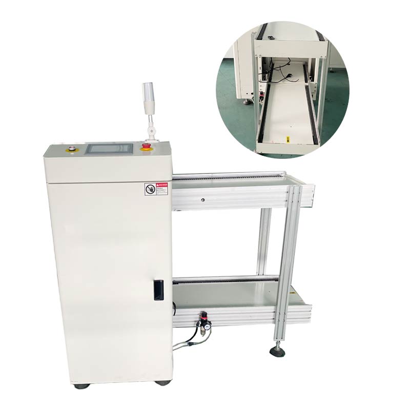
Factory floor layouts dictate equipment selection. You have to choose between compact designs and extended-magazine models. Compact loaders save valuable floor space in tight facilities but require operators to swap magazines more frequently. Extended-magazine models offer longer unattended operation times. They hold multiple racks simultaneously, which works well for high-volume, low-mix environments. Regardless of the footprint, fully enclosed models featuring safety covers are the industry standard. These enclosures prevent dust contamination on bare substrates. They also ensure CE-compliant operator safety by physically blocking access to moving pushers and lift platforms.
Metric | Manual Loading | Automated SMT Loader |
|---|---|---|
Cycle Time Consistency | Highly variable based on operator fatigue | Fixed, programmable transfer speeds |
Contamination Risk | High (skin oils, particulate transfer) | Low (enclosed, hands-free operation) |
ESD Hazard | High (requires strict wrist-strap compliance) | Low (grounded machine chassis and belts) |
Throughput Limit | Bottlenecks high-speed mounters | Paces the fastest downstream equipment |
Auditing equipment specifications against your facility's actual product mix is the first step in successful integration. Board dimensions, thickness, and weight tolerances vary wildly across different manufacturing sectors. Ultra-thin boards, often measuring 0.4mm or less, present severe warpage risks. If the pusher mechanism applies uneven pressure, these thin substrates bow and jam in the exit conveyor. Heavy backplanes or copper-clad power boards require robust lifting motors. You need reinforced magazine racks to prevent sagging and mechanical strain during the indexing process.
Magazine format compatibility dictates how materials enter the production line. Standard slotted magazines are the default for most SMT operations. They work perfectly when handling boards that are already assembled on one side. High-volume bare-board lines often utilize vacuum destackers. These machines lift unpopulated substrates directly from a stack, eliminating the need for slotted racks entirely. For odd-form substrates or highly specialized aerospace assemblies, emerging robotic loading systems offer programmable gripping solutions. Selecting the right format depends entirely on your board state and the required changeover frequency.
The dynamics of the pusher mechanism directly impact substrate integrity. Pneumatic pushers are common and cost-effective. However, they deliver abrupt force if air pressure fluctuates. Stepper-motor driven pushers provide superior control. They allow engineers to program specific thrust and speed profiles. A pcb loader machine equipped with a motorized pusher gently accelerates the board out of the magazine. It decelerates the board as it enters the downstream conveyor. This eliminates the risk of edge crushing on fragile materials.
Usability hinges on the Human-Machine Interface (HMI). Standard or customized English operation interfaces, along with multi-language support, drastically reduce operator error. An intuitive HMI simplifies troubleshooting by displaying clear diagnostic graphics rather than cryptic error codes. When a sensor is blocked or a magazine is misaligned, the interface pinpoints the exact location of the fault. This streamlines the initial setup process and minimizes downtime during live production.
Physical alignment dictates the success of every board transfer. A deviation of even a few millimeters between the loader and the solder paste printer causes catastrophic jams. Executing precise positioning checks requires specialized tools and a methodical approach.
Matching the exit height of the loader to the entrance conveyor of the downstream equipment is a precise mechanical process. Relying on visual estimates guarantees failure.
Position the equipment in its final designated location on the factory floor.
Place a digital inclinometer or a precision machinist level across the main chassis to verify absolute flatness.
Adjust the heavy-duty leveling feet independently until the X and Y planes are perfectly horizontal.
Measure the entrance height of the solder paste printer. This is typically standardized around 900mm ±20mm.
Adjust the Z-axis lift mechanism of the loader so the bottom of the board groove perfectly aligns with the printer's transport belts.
Lock the leveling nuts and verify that the machine does not rock or shift under applied weight.
Smooth board transition relies on perfect rail synchronization. In most SMT lines, the front rail serves as the fixed reference point. The rear rail adjusts dynamically based on board width. The fixed rail of the loader must perfectly collineate with the fixed rail of the printer. Use a precision straightedge to bridge the gap between the two machines, ensuring zero offset. Test the dynamic width adjustment by running the narrowest and widest boards in your product mix. Keep the transfer clearance gap between the two machines to an absolute minimum. A gap under 5mm prevents boards from skewing or dropping during the handoff.
Operators require unobstructed spatial clearances to safely swap heavy magazines. Ensure the factory layout provides adequate aisle space for manual handling or Automated Guided Vehicle (AGV) access. Test the magazine stack holder seating and locking mechanisms rigorously. A fully loaded magazine can weigh over 20 kilograms. If the locking clamps fail, the rack shifts mid-cycle. The pusher will strike the aluminum frame instead of the substrate. Verify that all safety covers are properly integrated. Opening a cover or breaching a light curtain must immediately halt the lift platform and pusher. This triggers an emergency stop state to protect the operator.
Mechanical alignment is useless without reliable machine-to-machine synchronization. The loader must know exactly when the downstream machine is ready to accept a board. The downstream machine must know when a board is en route.
The SMEMA standard has been the baseline for SMT line communication for decades. It utilizes a simple, hardware-based pin-level handshake. The loader sends a "Board Available" signal. The printer responds with a "Machine Ready" signal. Once both conditions are met, the conveyor activates. While highly reliable, SMEMA is limited to binary states. It cannot transmit data regarding board size, thickness, or barcode identifiers. Operators must manually adjust downstream equipment during product changeovers.
Modern smart factories are rapidly transitioning to the Hermes standard. Utilizing Ethernet-based communication, Hermes replaces the simple binary handshake with a data-rich exchange. When a PCB Loader indexes a new board, it passes a digital payload downstream. This payload contains the board's exact dimensions, thickness, and unique barcode data. Subsequent machines automatically adjust their rail widths and load the correct processing programs without human intervention. This drastically reduces changeover times and minimizes setup errors.
Feature | SMEMA (IPC-SMEMA-9851) | Hermes (IPC-HERMES-9852) |
|---|---|---|
Connection Type | Multi-core parallel cable (Hardware pins) | Standard Ethernet (TCP/IP) |
Data Transmitted | Binary states (Ready / Not Ready) | Board ID, Dimensions, Barcode, Recipe data |
Changeover Impact | Requires manual downstream adjustments | Enables automated, zero-touch changeovers |
Wiring Complexity | High (Thick cables, specific pinouts) | Low (Standard RJ45 network cables) |
Effective integration extends beyond the immediate downstream machine. The loader must communicate its operational status to the central Manufacturing Execution System (MES) or line control tower. If a magazine runs empty, a board jams, or a safety cover is breached, the equipment instantly broadcasts a specific error code to the MES. Line supervisors can dispatch technicians immediately, rather than waiting for downstream machines to report starvation. Comprehensive error logging enables predictive maintenance. It highlights recurring sensor faults or pneumatic drops before they cause catastrophic downtime.
A production line is a continuous system. Optimizing the front end requires equal attention to the back end. The rate at which materials enter the line must be perfectly balanced with the rate at which they exit.
Cycle time synchronization is a mathematical necessity. The feed rate of the loader must align with the extraction rate of the automatic pcb unloader. This machine is typically positioned post-reflow or post-AOI (Automated Optical Inspection). If the loader feeds boards faster than the unloader can rack them, Work-In-Progress (WIP) accumulates on the conveyors. This eventually triggers a line-wide halt. Engineers calculate the takt time of the slowest machine in the line, usually the pick-and-place or the reflow oven. They program the handling equipment to match that cadence, ensuring a steady, uninterrupted flow.
Micro-stoppages are inevitable in any complex manufacturing environment. To prevent these brief pauses from halting the entire line, buffer units must be integrated strategically. FIFO (First-In, First-Out) or LIFO (Last-In, First-Out) buffer conveyors sit between inspection equipment and the unloader. If the AOI machine flags a board for manual review, the buffer absorbs the incoming substrates. The loader and printer continue operating. Once the stoppage is resolved, the buffer releases the accumulated boards to the unloader at a controlled rate.
End-of-line magazine management presents a significant logistical challenge. The unloader constantly fills empty magazines with finished assemblies. The loader constantly empties them. Establishing a closed-loop system for returning empty magazines to the front of the line is critical. Many modern facilities utilize Automated Guided Vehicles (AGVs) to transport empty racks autonomously. This reduces reliance on manual labor. For facilities using manual carts, standardized staging areas and clear visual management (Kanban systems) ensure operators always have empty magazines available at the unloader and full magazines ready at the loader.
Deploying automated handling equipment introduces specific physical risks to the substrates. Anticipating these failures and implementing strict mitigation strategies protects high-value assemblies.
Substrates catch on the magazine slots or skew during the transition to the printer. This leads to crushed edges or snapped corners.
Implement strict sensor calibration routines.
Mandate the use of optical sensors to verify absolute board clearance before the next cycle initiates.
Utilize stepper-motor pushers with programmable tension.
If the pusher encounters abnormal resistance, program it to immediately retract and trigger an alarm rather than forcing the board forward.
Friction from conveyor belts and sliding boards generates static electricity. If this charge discharges into a bare substrate, it destroys sensitive components later in the assembly process.
Execute comprehensive grounding checks on the machine chassis, conveyor belts, and magazine racks.
Use a surface resistance meter to verify that all contact points fall within the safe dissipative range of 10^6 to 10^9 ohms/square.
Ensure operators wear grounded wrist straps when loading or unloading magazines.
Install static elimination ionizers above the magazine exit point for highly sensitive assemblies.
Factory air lines frequently experience pressure drops when multiple machines actuate simultaneously. This causes pneumatic pushers to stall or clamping cylinders to release prematurely.
Install dedicated air regulators and water traps directly at the machine inlet.
Set the regulator to the manufacturer's specified operating pressure, typically 0.4 to 0.6 MPa.
Monitor the gauge during peak line operation to identify supply drops.
The water trap prevents moisture from entering the pneumatic cylinders, preventing internal rusting and ensuring consistent pusher performance.
Audit your current line height and document the exact entrance specifications of your solder paste printer.
Measure and record the maximum and minimum dimensional variations of your board and magazine mix.
Request a physical protocol handshake test using SMEMA or Hermes with your downstream equipment vendor before finalizing procurement.
Establish a strict preventative maintenance schedule for sensor cleaning and pneumatic regulator checks.
A: The industry standard transfer height for SMT handling equipment is 900mm, with an adjustable variance of ±20mm. This allows the equipment to align perfectly with most global brands of solder paste printers and inspection conveyors. Always verify the exact entrance height of your specific downstream machine before adjusting the leveling feet.
A: Communication is handled via standardized protocols. Traditionally, this is done using the SMEMA standard, a hardware-based pin connection that sends simple board availability signals. Modern lines use the Hermes standard, an Ethernet-based protocol that transmits detailed board data, including dimensions and barcodes, alongside the readiness signals.
A: A magazine loader pushes boards out of slotted racks and is ideal for pre-assembled or double-sided boards. A vacuum destacker uses suction cups to lift bare, unpopulated boards directly from a stacked pile. A robotic handling system uses programmable arms and grippers to handle odd-form substrates or heavy backplanes.
A: Yes, provided the unloader is specifically designed with a traversing mechanism or dual-lane indexing capabilities. The unloader must be able to shift its receiving conveyor to align with either lane of the reflow oven. Its cycle time must be fast enough to extract boards from both lanes without causing backups.
A: Prevent scratching by ensuring perfect Z-axis height alignment and X/Y-axis rail synchronization. Use stepper-motor driven pushers to apply smooth, controlled force rather than abrupt pneumatic strikes. Ensure the magazine slots are free of debris and that the conveyor belts are manufactured from ESD-safe, non-abrasive materials.
A: Enclosed designs serve two critical functions. First, they provide CE-compliant physical barriers, protecting operators from pinch points and moving lift platforms. Second, they act as environmental shields, preventing factory dust and airborne contaminants from settling on bare copper pads before the solder paste printing process.
A: Most standard loaders require a single-phase AC 220V or 110V power supply. For compressed air, they typically require a clean, dry supply regulated between 0.4 and 0.6 MPa. Dedicated air regulators and water traps are highly recommended to maintain consistent pneumatic performance and prevent cylinder damage.