Views: 0 Author: Site Editor Publish Time: 2026-10-10 Origin: Site
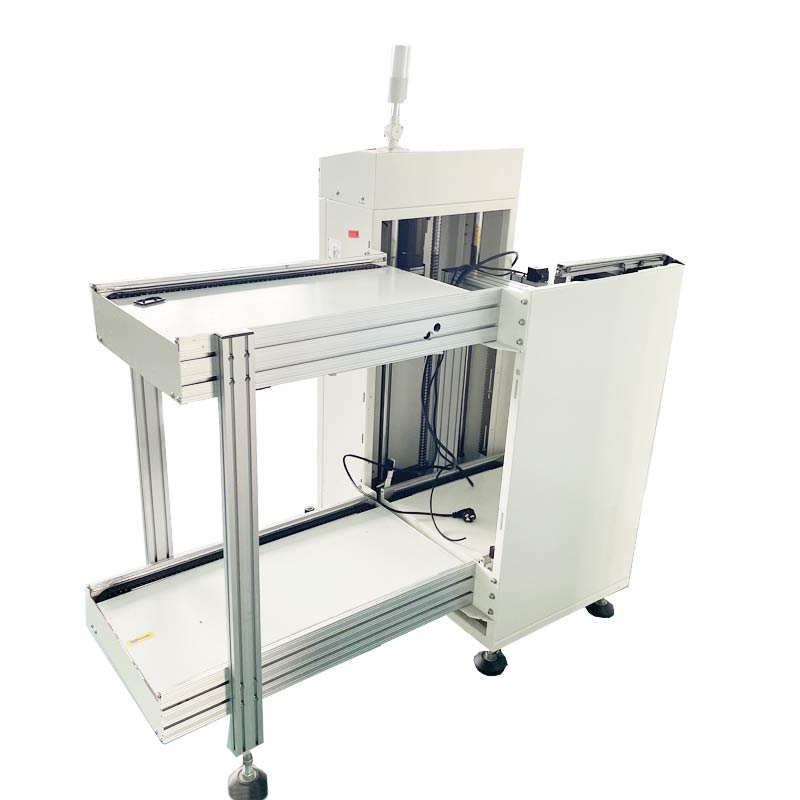
Picture a high-volume factory floor. A single misstep here causes a cascade of delays. In modern Surface Mount Technology production environments, seamless communication between distinct pieces of equipment is the absolute backbone of manufacturing efficiency. At the very genesis of this assembly line sits the pcb loader machine. This critical apparatus is responsible for feeding bare or partially assembled boards into downstream processes like solder paste printers and high-speed pick-and-place systems.
How do we guarantee these individual components work together harmoniously? We must prevent substrates from crashing. We must eliminate severe bottlenecks. To achieve this, the electronics manufacturing sector relies heavily on the SMEMA standard. Comprehending and executing a meticulously structured signal testing workflow for your board feeding equipment is non-negotiable. You must do this before transitioning into full-scale production. Overlooking a single misconfigured relay can lead to catastrophic board jams. It can dislodge micro-components or trigger total line halts that bleed profitability. This comprehensive guide breaks down the procedural diagnostic workflow. It addresses troubleshooting strategies for common communication errors and highlights crucial considerations when evaluating board handling technology for your facility.
Standardized Communication: The protocol utilizes a straightforward yet highly reliable dry-contact signal framework. This synchronizes the feeding equipment with subsequent workstations.
Mandatory Diagnostics: Implementing a strict signal verification routine actively prevents physical damage to delicate substrates. It also mitigates exorbitant production downtime.
Holistic Integration: Diagnostic procedures must account for the entire manufacturing ecosystem. This spans from the initial feeding stage all the way to the automated unloading systems at the line terminus.
Efficient Troubleshooting: A vast majority of synchronization failures originate from elementary wiring faults. Misconfigured PLC logic or mismatched pin assignments are more common than catastrophic hardware failures.
Strategic Procurement: Investing in contemporary board handling machinery equipped with built-in diagnostic interfaces streamlines the integration process dramatically.
Before initiating any diagnostic procedures, technicians must possess a firm grasp of the underlying communication framework. The SMEMA standard acts as a universal language for SMT equipment. It bridges the gap between disparate brands and generations of machinery. At its core, the standard relies on a universally recognized 14-pin connector. It operates on a dry-contact logic system, typically fluctuating between 0V and 24V.
The operational logic is elegantly simple. The Board Available signal is the loader announcing to the adjacent workstation that a substrate is queued and ready for transfer. Conversely, the Machine Ready signal acts as the downstream equipment response. It confirms that its internal conveyor is clear and positioned to accept the incoming panel. This standardized handshake allows factory managers to mix and match different equipment. They can weave them into a singular, cohesive manufacturing line without requiring bespoke software integration.
Moving beyond theoretical knowledge, proper physical and mechanical staging is imperative. You must establish this before any electrical currents are introduced. Establishing a safe baseline ensures accuracy during the diagnostic phase. It also protects operators from unexpected mechanical movements.
Begin with precise physical alignment. Operators should utilize leveling tools to verify that the conveyor height and rail width of the board feeding apparatus perfectly match the receiving workstation specifications. Furthermore, once aligned, grab a flashlight and meticulously inspect the 14-pin SMEMA cables. Look for bent pins, frayed insulation, or loose internal connections that could cause intermittent signal drops. Next, navigate the machine touchscreen or PLC interface to confirm the communication mode is explicitly toggled to the ON position. Crucially, always depress the bright red emergency stop buttons during the initial wiring check. This tactile safety measure prevents sudden mechanical actuation from catching your fingers off guard while probing the electrical contacts.
With the physical staging complete, technicians can move into the core operational procedure for validating electrical communication. This sequential approach isolates variables. It makes pinpointing exact points of failure significantly easier.
The first phase involves simulating a receptive state from the downstream equipment. By utilizing a dedicated tester or a carefully placed jumper wire, technicians can mimic the Machine Ready signal. Observe the PLC interface or indicator lights to verify that the system successfully registers this external input. This confirms its receiving circuitry is fully functional.
Once the input is validated, attention shifts to the output. Manually trigger the feeding apparatus to advance a dummy board onto its exit conveyor. During this mechanical action, employ a digital multimeter across the appropriate pins. Confirm the system is generating the correct voltage or contact closure. This proves the machine can successfully broadcast its Board Available status.
Theoretical simulations must eventually give way to practical application. Connect the feeding mechanism directly to the actual downstream machine using the verified 14-pin cable. Run a test substrate through the sequence to observe the mechanical and electrical handshake in real-time. Specifically, the pusher mechanism should halt its advance the exact millisecond the receiving workstation drops its Ready signal. This prevents any forceful collisions.
Even with a meticulously executed setup routine, complications can arise in a real-world manufacturing environment. Knowing how to swiftly diagnose and rectify these bottlenecks is what separates an average operator from a master technician.
Have you ever hit the start button only to watch the feeding mechanism stubbornly hold onto the panel? This paralysis typically stems from a missing Machine Ready signal from the downstream workstation. Occasionally, it points to a degraded internal relay within the loader itself. In contrast, if you experience board crashes or double-feeding, the culprit is often a Board Available signal stuck in the closed position. In such instances, technicians must clean the optical sensors, check for ambient light interference, and reset the PLC logic.
Wiring reversals represent another frequent headache. When utilizing custom-built or field-repaired cables, wires frequently become crossed. Technicians often confuse Pins 1 and 2 with Pins 3 and 4. A quick continuity check with a multimeter can identify this reversal, allowing for a rapid re-pinning of the connector.
Analyzing broader industry trends reveals a significant evolution in these communication workflows. As manufacturing pivots toward Industry 4.0 and smart factory environments, the traditional SMEMA workflow is being augmented. We are seeing a rapid adoption of advanced protocols like SECS/GEM and IPC-CFX across the globe. These modern frameworks allow for rich, bidirectional data exchange rather than just simple binary signals. They transmit data regarding board traceability, recipe management, and predictive maintenance alerts.
However, industry experts emphasize a critical reality. The fundamental dry-contact handshake remains the bedrock of line synchronization. Without verifying this basic electrical integrity first, advanced IoT analytics and predictive maintenance algorithms cannot function reliably. Upgrading to smart factory standards requires a flawless foundational signal workflow.
For procurement specialists and production managers looking to future-proof their assembly floors, selecting equipment with the right feature set makes integration and diagnostic testing nearly effortless. You need to look at real-world parameters to make an informed decision.
When evaluating an smt pcb loader, prioritize machinery equipped with robust programmable logic controllers and intuitive touchscreens. A high-quality unit will feature a visual I/O status screen directly on its display. This completely eliminates the need for technicians to probe pins with external multimeters during routine checks. Let us look at a practical parameter comparison to guide your selection process.
Feature / Parameter | Standard Bare Board Loader | Advanced Magazine Loader |
|---|---|---|
Control System | Basic Microcontroller | Panasonic PLC + User-friendly Touch Screen |
PCB Size Compatibility | Fixed sizes up to 250x250mm | Adjustable: 50x50mm up to 460x330mm |
Step Pitch Selection | Fixed pitch | Selectable: 10, 20, 30, 40mm |
Communication Protocol | Standard SMEMA | Standard SMEMA with IPC-CFX readiness |
Pneumatic Pressure | N/A or minimal | 4 to 6 kgf/cm² for stable magazine lifting |
Verify universal compatibility. The hardware should support standard global protocols natively, without relying on fragile custom adapters. Finally, insist on robust sensor technology. Premium optical sensors that reliably detect varying board colors and textures guarantee that the availability signal triggers at the exact right millisecond.
It is worth noting that this rigorous diagnostic methodology is not exclusive to the beginning of the assembly process. The exact same logical workflow is mirrored at the end of the line. For instance, when configuring an automatic pcb unloader, technicians must ensure the equipment accurately broadcasts its readiness to receive finished assemblies. This safeguards valuable, fully populated boards from overflowing or stacking improperly into storage magazines. The unloader relies on a robust pusher cylinder and precise step pitches to index the boards safely.
Connecting technical diagnostic procedures to bottom-line business outcomes is crucial for factory management. A flawlessly integrated SMT line effectively eradicates the infuriating micro-stoppages that plague poorly optimized facilities. While a ten-second delay waiting for a sensor to trip might seem trivial, those moments aggregate. They quickly turn into hours of lost production capacity over a fiscal quarter.
Furthermore, precise signal timing acts as a physical safeguard. It ensures delicate substrates are not crushed between misaligned conveyors. This protects expensive microprocessors and fragile ceramic components from mechanical stress. As lines become more sophisticated, these verified signals work in tandem with factory execution software, feeding highly accurate throughput data directly to production managers in real-time.
A rigorous, well-documented signal verification workflow is undeniably the unsung hero of a highly efficient surface mount production line. By taking the deliberate time to validate the inputs, outputs, and physical handshakes of your board handling equipment, you actively insulate your manufacturing schedule against unnecessary downtime. You also prevent costly material scrap.
Whether you are commissioning a brand new feeding apparatus or troubleshooting an existing automated unloading system at the packaging stage, standardizing your diagnostic procedures is a proven strategy. It elevates overall factory throughput. As you look toward future capital investments, prioritize machinery with intuitive logic controls, versatile PCB size compatibility, and integrated diagnostic tools. To explore equipment that meets these exact rigorous standards and seamlessly integrates into your smart factory, visit https://www.smtwenzhan.com to find the right brand and product configurations for your specific production needs.
The Surface Mount Equipment Manufacturers Association standard is a universally adopted communication protocol. It enables disparate pieces of SMT machinery—such as board feeders, screen printers, and automated optical inspection units—to communicate seamlessly using basic, standardized Board Available and Machine Ready electrical signals.
This interruption almost always occurs because the feeding mechanism is not receiving the requisite Machine Ready signal from the adjacent downstream equipment. To resolve this, technicians should inspect the interconnecting cable, verify the downstream machine is not paused in an error state, and ensure the internal PLC communication settings are configured correctly.
Absolutely. Technicians routinely use dedicated testing tools or a simple combination of a jumper wire and a digital multimeter to simulate downstream responses. This allows operators to verify that internal relays, optical sensors, and PLC logic are functioning perfectly before introducing another complex machine into the equation.
Equipment stationed at the beginning of the assembly process is designed to introduce bare or partially assembled substrates into the manufacturing flow. Conversely, unloading equipment sits at the very terminus of the line. It is tasked with safely receiving finished, populated boards and carefully indexing them into storage magazines. Despite their opposite physical roles, both systems rely entirely on the same standardized communication signals to coordinate their mechanical movements.
Signal verification should be a mandatory procedure during initial factory installation. You must also perform it anytime a piece of machinery is physically relocated, immediately following the replacement of communication cables, or after any significant maintenance is performed on the internal logic controllers or optical sensor arrays.
Testing a cable requires a standard digital multimeter set to the continuity or resistance function. Technicians probe Pin 1 to Pin 1, Pin 2 to Pin 2, and so forth across both ends of the cable. This ensures there are no internal breaks in the wire and verifies that the pins have not been accidentally crossed or reversed during a previous repair.
The standard relies on a dry-contact logic system. When a signal is active, the circuit closes, typically allowing a 24V DC signal to pass through, though some legacy systems might operate on lower voltages. The critical factor is that the equipment relies on the closure of the contact relay rather than transmitting a specific power load.