Views: 0 Author: Site Editor Publish Time: 2026-10-23 Origin: Site
Manufacturing modern electronics requires assembling boards with a staggering mix of component sizes. From microscopic 01005 chips that look like specks of dust to bulky connectors and complex BGAs, the physical variance is immense. Placing these mixed components randomly on feeder racks is a recipe for inefficiency. It leads to excessive placement head travel time. It also causes frequent nozzle changes. Ultimately, this results in a drastic drop in production throughput. Watching a gantry waste precious seconds traveling back and forth across a 1.5-meter rack highlights this bottleneck perfectly.
The solution lies in strategic feeder position planning. By mapping out exactly where each reel, tube, and tray should sit, manufacturers can unlock the true potential of any pick and place machine. This guide walks you through exact strategies, equipment considerations, and practical processes needed to optimize feeder layouts for highly mixed component assemblies.
Strategic grouping saves time: Grouping mixed components by nozzle type and physical size minimizes tool changeovers. This drastically reduces placement head travel distance.
Machine type dictates strategy: The ideal layout for a highly adaptable machine differs fundamentally from that of a pure chip shooter. Each architecture requires a tailored approach.
Software is your best friend: Modern offline programming software automatically simulates, tweaks, and optimizes feeder arrangements before a single board enters the production line.
Advanced equipment offers an edge: Leading automated systems provide intelligent feeder carts and dynamic software integration. These features simplify the complex task of mixed component planning.
In Surface Mount Technology assembly, milliseconds matter. The distance between a specific feeder slot and the exact placement coordinate on the PCB dictates the X-Y gantry travel time. When this distance is optimized, the placement head moves in short and efficient bursts. Shaving just a fraction of a second off each component placement translates to massive cycle time gains over a full production shift. Consequently, poor layout forces the machine into long diagonal sweeps. This bleeds efficiency with every cycle.
Furthermore, mixed components encompass everything from standard passive resistors to intricate ICs and odd-form parts. Differing heights, weights, and packaging types complicate the feeding process. They demand careful spatial planning to prevent mechanical interference. A tall electrolytic capacitor placed carelessly next to a tiny 0402 resistor feeder can obstruct the placement head's downward stroke. This often causes costly collisions or mis-picks.
High-mix, low-volume environments introduce unique variables. The physical dynamics of part feeding require strict attention. Heavier or larger components often demand slower pick-up speeds. This maintains feeding uniformity and prevents the part from shifting inside the tape pocket during head movement. A flexible SMT placement machine, such as the JUKI RS-1XL, must balance these delicate picks with rapid movements for smaller parts. The RS-1XL boasts a variable mounting speed up to 42,000 CPH and handles components from 0201 metric up to 74mm square. Grouping similar-weight items based on these parameters is crucial for maintaining a rhythmic machine cadence.
In addition, adaptable machines frequently switch nozzles to accommodate diverse parts. Every trip to the nozzle exchange station pauses actual placement. By clustering components that share the exact same nozzle type close to one another on the feeder bank, engineers minimize the time the machine spends swapping tools. This sequential picking strategy keeps the head productive for longer stretches before a tool change is mandated.
A golden rule of SMT programming is to prioritize your highest-volume parts. High-runner standard components should be placed centrally on the feeder bank. Keep them as close to the PCB conveyor as possible. This minimizes the longest travel distances for the parts that the machine must fetch most frequently. Keeping them clustered near the board's center of gravity drastically reduces overall X-Y travel time.
In contrast, bulky, tall, or odd-form components require a defensive placement strategy. Position these larger items toward the outer edges of the feeder rack. This deliberate segregation prevents towering components from obstructing the placement head's flight path as it zips back and forth carrying smaller parts. Isolating them also reduces the risk of mechanical collisions with adjacent densely packed 8mm feeders.
Component Type | Recommended Feeder Position | Grouping Strategy | Primary Goal |
|---|---|---|---|
High-Volume Passives | Center of the feeder rack | Group by identical nozzle type | Minimize X-Y travel distance |
Large ICs & Connectors | Outer edges of the rack | Isolate from low-profile chips | Prevent Z-axis collisions |
Heavy/Odd-Form Parts | Rear bank or isolated slots | Group by similar pick speed | Maintain vacuum stability |
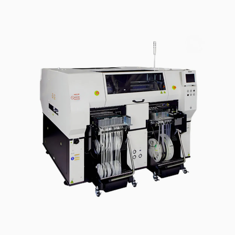
High-speed chip shooters operate on a different paradigm. A high speed SMT placement machine typically utilizes multi-spindle inline heads or rotary turrets designed to pick up several components simultaneously. For example, the Panasonic AM100 features a single 14-nozzle head capable of placing an impressive 35,800 CPH while handling diverse component mixes. To maximize this architecture, engineers employ gang picking. This involves arranging feeders sequentially with matching pitch spacing. The head can then descend once and pick multiple parts in a single synchronized downward stroke.
Specifically, many high-throughput systems feature front and rear feeder banks served by dual gantries. The secret to maximizing output here is workload synchronization. Components must be split logically across both banks to balance the placement burden between the two heads. If all high-volume parts are loaded onto the front rack, the rear gantry will sit idle. Proper distribution ensures both heads work continuously in tandem.
Modern equipment leverages technology to eliminate human error from the setup equation. For instance, a Panasonic pick and place machine often utilizes smart RFID-enabled feeders and intelligent carts. These devices automatically communicate their exact physical position and loaded component data directly to the machine's mainframe. If an operator accidentally slots a 10k resistor where a 1k resistor should be, the machine flags the error instantly. This prevents disastrous mixed-component builds.
Furthermore, hardware is only half the battle. Proprietary software completes the optimization loop. Advanced platforms automatically calculate the most efficient feeder layout based on the imported Bill of Materials and CAD data. By analyzing travel routes and nozzle requirements, the software drastically reduces manual planning time.
Looking at the broader manufacturing landscape, the trend is shifting heavily toward AI-driven digital twins and predictive layout planning. Historically, feeder positioning was a static process set once per production run. Today, industry analysts note that smart factories are utilizing machine learning algorithms to analyze historical placement data. These algorithms dynamically suggest feeder reallocations on the fly. As production shifts from one mixed-component board to another, the software identifies the exact sequence of feeder cart swaps needed to minimize downtime. The integration of real-time inventory tracking with feeder optimization is rapidly becoming the standard for modern agile electronics manufacturing.
Begin by analyzing your BOM and CAD data. Import your coordinates into your programming environment. Categorize all parts by total quantity required per board, physical dimensions, and packaging format. Identifying your high-runners and your odd-form outliers early establishes a solid baseline strategy.
Next, group components by nozzle and height. Create a matrix to cluster parts logically. First, group parts that utilize the same nozzle type to encourage sequential picking. Then, review the Z-axis height data. Ensure that tall components are grouped away from low-profile chips. This prevents the placement head from performing extreme and time-consuming Z-axis retractions.
Finally, run simulation and optimization software. Never test a new layout on a live machine. Utilize offline programming software to simulate the production run. Let the system's algorithm suggest a baseline layout. Manually tweak it to account for specific physical constraints on your shop floor.
A frequent and frustrating error is ignoring the physical width of the feeders themselves. Placing large tape feeders too close to standard 8mm slots often causes mechanical interference. The locking levers may rub against one another. Always leave adequate blank slots between wide feeders to ensure smooth operation.
Moreover, failing to account for the vibration dynamics of a fully loaded feeder rack leads to subtle defects. Hearing the distinct rattle of an improperly seated heavy component is a major red flag. Excessive vibration from rapid machine movements causes parts in adjacent lanes to bounce inside their tape pockets. Secure heavy components properly and space them away from ultra-lightweight 01005 chips to maintain strict feeding uniformity.
Planning feeder positions for mixed components is a delicate balancing act. It requires minimizing X-Y travel distances and intelligently grouping parts by nozzle type. A well-planned feeder rack is the foundation of a smooth and error-free production run.
Whether you are running a flexible setup for rapid prototyping or a high-speed inline system for mass production, feeder optimization remains the lowest-hanging fruit for boosting your return on investment. The time spent planning in the virtual environment pays massive dividends on the physical shop floor.
Evaluate your current SMT line efficiency today. If your placement heads are traveling further than they need to, it is time for an upgrade. We invite you to explore advanced automated systems that take the guesswork out of feeder planning. Find the perfect brand and product to match your production needs by visiting https://www.smtwenzhan.com.
CPH is heavily dependent on the X-Y gantry travel time. Poor feeder placement forces the placement head to travel longer distances between the pick-up point and the PCB coordinate. This increased travel distance lowers the realized CPH significantly compared to the theoretical maximum rating.
No, different architectures require completely different approaches. High-speed systems typically rely on gang-picking arrangements where multiple adjacent parts are picked simultaneously. Adaptable machines require layouts optimized for frequent nozzle changes and the safe handling of diverse component shapes.
Tall components should be placed on the outer edges of the feeder banks and grouped together. This strategic placement prevents the placement head from having to constantly jump over them to reach smaller parts. It reduces unnecessary Z-axis travel time and mitigates the risk of mid-air collisions.
Modern equipment utilizes RFID or barcode-enabled smart feeders combined with offline optimization software. These systems automatically calculate the most efficient physical layout. They verify that the correct component is loaded into the exact correct slot before production begins.
Every time a machine stops to change a nozzle, it loses valuable production time. By grouping components that require the same nozzle close together on the feeder rack, the machine can pick and place multiple parts consecutively. This reduces the total number of tool changes per board.
Heavy components require slower gantry acceleration to prevent them from shifting on the nozzle during transit. If heavy parts are mixed randomly with lightweight parts, the machine must constantly adjust its speed profile. Grouping heavy components allows the machine to optimize its speed settings for specific sections of the run.