Views: 0 Author: Site Editor Publish Time: 2026-10-15 Origin: Site
Achieving the perfect solder joint in Surface Mount Technology, commonly known as SMT, is a strict engineering challenge. Without highly accurate, real-time temperature tracking, manufacturers risk producing printed circuit boards plagued by cold solder joints, tombstoning, or thermally degraded components. Specifically, many process engineers struggle to select the appropriate process control equipment. They are often unsure of exactly how many measurement channels they need to monitor their specific board assemblies effectively.
The definitive solution for validating and optimizing oven temperatures is a reliable thermal profiler for reflow oven. However, not all data acquisition units are configured equally. The ideal number of input channels depends entirely on the physical complexity of the board, the density of its components, and the specific thermal tolerances demanded by chip suppliers. In this comprehensive guide, we will explore how to evaluate your facility's channel requirements. We will also break down the technical variables influencing these decisions and highlight the essential features to prioritize when investing in industrial-grade profiling hardware.
To fully grasp the importance of channel requirements, one must first understand the core mechanics of the equipment. A thermal profiler for reflow oven is a sophisticated, heat-shielded data logger designed to travel along the conveyor belt right alongside the PCB. As the assembly transitions through the preheat, thermal soak, time above liquidus, and cooling zones, the internal microprocessors record temperature fluctuations at precise, fraction-of-a-second intervals.
In the context of thermal mapping, channels refer to the individual thermocouple inputs. These are typically highly sensitive Type K wires that line operators attach directly to various components across the circuit board. Each channel functions as an independent, localized temperature sensor.
Furthermore, the necessity for multiple channels stems from the physical reality of thermal mass. Different components on a single substrate absorb and dissipate heat at drastically different rates. For example, a massive copper power transformer will act as a heat sink. It warms up much slower than a microscopic 0201 passive resistor located just millimeters away. An engineer might only measure the temperature of the tiny resistor. This flawed data will falsely indicate a successful reflow. Meanwhile, the solder beneath the heavy transformer remains a cold, unbonded paste. Consequently, deploying an adequate number of channels is the only way to capture the complete thermal delta across the entire manufacturing assembly.
Selecting the optimal channel configuration requires a pragmatic assessment of your current production floor realities. It also requires a forward-looking view of your future manufacturing pipeline. To simplify this engineering decision, refer to the core comparison table below.
| Channel Count | Board Complexity | Target Application | Recommended Hardware Spec |
|---|---|---|---|
| 4 to 6 Channels | Low complexity, single-sided, uniform components | Basic consumer electronics, simple LED boards | Basic data logger with standard heat shield |
| 9 Channels | Medium to high complexity, high-mix boards, standard BGAs | Industrial controls, standard automotive, telecom | KIC Start 9-channel equivalent, robust measuring range |
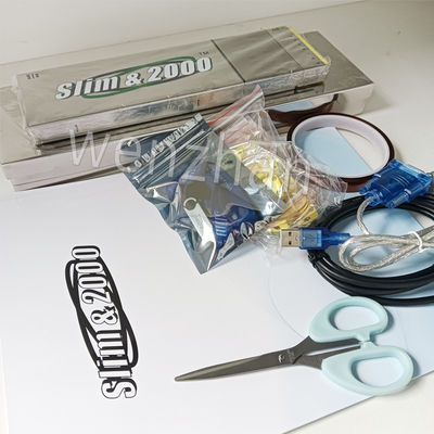
| 12 to 24+ Channels | Ultra-high density, multi-layer, heavy copper planes | Aerospace, EV power boards, military electronics | Slim KIC 2000 12-channel equivalent, high sampling rate |
Recent industry analyses reveal a distinct, accelerated shift in thermal profiling requirements. Consumer electronics are aggressively pursuing miniaturization through High-Density Interconnect designs. Simultaneously, the electric vehicle sector demands ultra-reliable, heavy-copper power boards. Because of these advancements, the margin for thermal error has practically vanished. Lead-free solder pastes now require significantly tighter process windows compared to traditional tin-lead alloys.
Consequently, the reliance on basic four-channel units is rapidly declining across the sector. Manufacturing facilities are increasingly adopting 9-channel or 12-channel systems as the baseline standard. This upgrade guarantees compliance with stringent automotive and aerospace quality certifications, ensuring that even the most complex, densely packed boards are profiled with absolute precision.
Several physical and technical variables dictate exactly how much diagnostic visibility your profiling equipment must possess to ensure a zero-defect soldering process.
The physical footprint of the printed circuit board directly dictates its thermal behavior inside the heating tunnel. Large substrates inherently experience extreme temperature variations across their surface area. Typically, the outer edges of a large PCB will reach liquidus temperatures minutes before the dense geometric center. A robust channel count allows process engineers to place sensors at all critical extremities and central zones. This ensures the center reaches the required temperature without thermally degrading the sensitive components located on the edges.
Modern component packaging presents unique profiling hurdles. Because the solder joints of Ball Grid Arrays and Chip Scale Packages are completely hidden beneath the component body, engineers must carefully route microscopic thermocouples underneath the package to measure the actual solder balls. Complex boards often feature multiple hidden arrays. You will need dedicated channels just to monitor these internal joints alongside the rest of the board's surface components.
Solder paste formulators and microchip fabricators issue strict thermal boundaries that must be respected during the heating cycle. These specifications dictate the maximum allowable ramp rate, the exact time above liquidus, and the absolute peak temperature thresholds. To guarantee field reliability, you must have enough measurement points to prove that every single critical component stays within its designated OEM reflow soldering profile window. A limited channel count simply cannot provide the empirical evidence required to validate these stringent supplier specifications across a complex board.
When evaluating capital equipment for process control, the raw number of channels is just one piece of the puzzle. The physical construction and analytical software capabilities are equally critical to your success on the factory floor.
The interior atmosphere of a reflow machine is exceptionally hostile. Beyond the extreme peak temperatures that easily exceed 250 degrees Celsius, the oven is saturated with vaporized flux off-gassing and volatile organic compounds. Over time, these corrosive elements will penetrate standard casings and destroy sensitive internal microelectronics. Therefore, it is highly recommended to procure a corrosion resistant kic reflow profiler. Units equipped with hermetically sealed, high-grade stainless steel or specialized ceramic thermal shields protect the data logger. This robust construction ensures accurate calibration and extends the operational lifespan of the hardware over thousands of production runs.
A measurement device is only as powerful as the software interpreting its data. Modern profiling systems must include advanced predictive analytics. Instead of relying on archaic trial-and-error methods, high-end software algorithms can automatically calculate the Process Window Index. The software then proactively suggests precise adjustments to specific oven heating zones and conveyor belt speeds. This drastically reduces setup times for new product introductions.
Managing a dozen long, thin thermocouple wires can be a logistical nightmare for line operators. Tangled wires lead to damaged sensors and inaccurate readings due to poor component contact. When selecting equipment, prioritize systems designed with organized cable management, color-coded inputs, and quick-disconnect plugs. These practical features reduce frustration on the factory floor and minimize the risk of setup errors.
In the highly specialized realm of thermal process control, certain equipment architectures stand out for their precision engineering. Utilizing a Manual KIC Thermal Profiler provides process engineers with an unparalleled degree of hands-on control. This granular control is particularly vital during the initial New Product Introduction phase.
Manual profiling allows engineers to meticulously select the most thermally challenging test points. They can securely anchor the thermocouples themselves, gathering high-resolution data that automated, non-contact systems might overlook. These profilers, such as the Slim KIC 2000 series, are renowned for their exceptionally high sampling rates. They capture transient temperature spikes down to fractions of a second. By leveraging this hyper-accurate data, manufacturers can fine-tune their oven recipes to achieve near-zero defect rates and maximize their first-pass yields.
Owning a high-capacity, multi-channel data logger is only effective if the equipment is deployed methodically. Following a structured engineering methodology ensures that all components remain safely within their operating limits.
For manufacturing executives and process engineers finalizing a procurement decision, justifying the capital expenditure for advanced, multi-channel profiling equipment requires a pragmatic risk assessment.
A basic 4-channel profiler carries a lower initial acquisition cost. However, it introduces a massive diagnostic blind spot into your quality control process. The financial risk associated with insufficient thermal data is severe. If an entire batch of complex, multi-layer PCBs is scrapped due to undetected cold solder joints or heat-induced component degradation, the cost of the lost materials, wasted labor, and missed deadlines will far exceed the price difference between a basic unit and a high-end model.
Investing in a 9-channel or 12-channel system serves as a critical risk mitigation strategy. Furthermore, purchasing a profiler with slightly more channels than you currently need is a highly prudent method of future-proofing your production line. As electronic designs inevitably become denser and more complex, possessing a high-capacity profiler ensures your facility remains fully capable of meeting stringent industry standards without necessitating immediate, unexpected equipment upgrades.
The determination of how many channels a thermal profiler for reflow oven requires is intrinsically tied to the physical and thermal complexity of the printed circuit boards being manufactured. There is no universal, one-size-fits-all configuration. Rather, the choice must be dictated by your facility's specific empirical production requirements.
While 4 to 6 channels may suffice for basic, single-sided consumer goods, modern SMT manufacturing demands a much higher degree of thermal visibility. A 9 to 12-channel configuration provides the comprehensive, localized data necessary to map extreme thermal mass variations accurately. This granular level of detail is the only objective way to ensure strict compliance with component specifications and solder paste requirements, ultimately preventing costly defects.
If your facility is looking to eliminate soldering defects and optimize production yields, taking action is essential. Manufacturers are strongly encouraged to critically evaluate their current board designs and upgrade their profiling hardware accordingly. For a comprehensive range of industry-leading process control equipment, visit https://www.smtwenzhan.com to find the exact brand and product configuration that perfectly matches your thermal profiling requirements.
The accepted industry standard for most mid-to-high complexity SMT production lines is 9 channels. This configuration offers an optimal balance, providing thorough thermal coverage for the board's corners, geometric center, and critical components, while remaining highly manageable for the line operator to set up efficiently.
A 6-channel unit limits you to basic edge and center monitoring, leaving large blind spots on complex boards. In contrast, a 9-channel unit allows for comprehensive, simultaneous mapping of hidden BGA centers, heavy copper planes, and sensitive integrated circuits. This extra data is critical for preventing localized cold solder joints on high-density assemblies.
Reflow ovens contain a highly aggressive atmosphere filled with vaporized flux residues and operate at extreme peak temperatures. A corrosion-resistant thermal shield acts as a critical barrier. It protects the sensitive internal electronics of the data logger from chemical degradation and heat damage, thereby significantly extending the lifespan and accuracy of your investment.
To maintain measurement integrity and comply with ISO quality standards, industrial thermal profilers should typically be calibrated annually. However, facilities running high-volume, 24/7 operations in highly corrosive oven environments may require bi-annual calibration checks to ensure sensor drift does not compromise the reflow data.
Yes, many advanced thermal profilers are versatile enough to be utilized in wave soldering applications. However, it is imperative that you equip the data logger with a wave-specific thermal shield and utilize dedicated wave soldering thermocouple fixtures. This protects the equipment from direct, catastrophic contact with the molten solder wave.
Your thermal profiler's analytical software will automatically overlay your actual, measured board temperatures from all active channels against the component manufacturer's specified tolerance limits. The software then calculates a statistical metric known as the Process Window Index to objectively confirm whether your soldering process is fully compliant and safe.