Views: 0 Author: Site Editor Publish Time: 2026-10-29 Origin: Site
As much as 70 percent of surface mount technology defects trace back to the printing stage. If you skip rigorous checks, hidden flaws like insufficient paste or subtle bridging will slide downstream. This inevitably leads to scrapped circuit boards and massive rework costs. A robust inline inspection system acts as your ultimate gatekeeper. It stops these costly errors dead in their tracks before components are ever placed.
Looking at the broader manufacturing landscape, the relentless push toward ultra-miniaturization is reshaping production lines. With 01005 and 0201 metric packages becoming standard, relying on human eyes is a recipe for disaster. We are seeing an aggressive industry-wide shift toward zero-defect, AI-driven closed-loop manufacturing. Consequently, deploying inline 3D scanning technology is no longer a mere quality assurance luxury. It has become a strict compliance mandate for high-stakes sectors like automotive, medical, and aerospace. In this guide, you will learn the exact engineering steps to seamlessly integrate this critical equipment into your factory floor.
Key Takeaways
To maximize manufacturing yields, you have to control variables right at the start of the assembly process. The inspection unit functions as your primary diagnostic tool. It translates physical paste deposits into hard, actionable data.
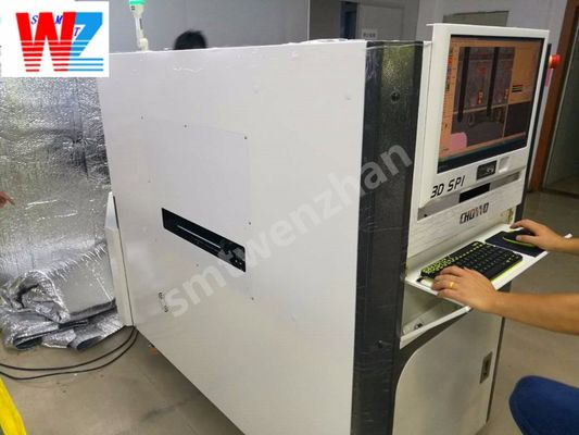
Modern Solder Paste Inspection is a highly precise automated process used to evaluate the quality of solder paste deposited onto a printed circuit board. Utilizing advanced 3D optical sensors, the equipment measures the volume, height, area, and shape of every single solder paste deposit in real-time. By comparing these physical measurements against predefined engineering tolerances, the system identifies insufficient paste, excessive volume, bridging, and misalignment.
There is a massive operational difference between offline benchtop systems and inline machines. Offline units are fine for batch sampling and initial process setup. However, they require manual board handling and simply cannot keep pace with high-speed production lines.
Furthermore, mounting the equipment directly inline offers continuous, real-time feedback to the paste printer. This setup creates a powerful closed-loop process. If the optics detect a trending deviation, such as paste volume gradually decreasing across consecutive boards, the system automatically signals the printer. The printer can then adjust squeegee pressure, change the separation speed, or trigger a stencil cleaning cycle. This proactive intervention prevents defects from ever reaching the reflow oven.
Before moving any heavy machinery, facility preparation is critical. Preparing the exact location ensures a safe installation process and prevents unnecessary line downtime.
An inline optical system requires highly specific environmental conditions to function reliably. You must verify the physical footprint first. Ensure there is adequate floor space not just for the chassis, but also for operator access, maintenance doors, and proper ventilation.
| Requirement Category | Standard Specification Parameters | Engineering Purpose |
|---|---|---|
| Power Supply | 220V AC ±10 percent, Single Phase, 50/60Hz | Ensures stable operation of sensitive optical sensors and drive motors. |
| Grounding | Less than 10 Ohms resistance | Prevents static discharge and electrical interference from skewing data. |
| Pneumatics | Clean, dry air at 0.4 to 0.6 MPa | Powers internal conveyor belts and the rigid PCB clamping mechanisms. |
| Floor Bearing | Minimum 500 kg per square meter | Supports the heavy cast-iron frame required for vibration damping. |
| Environment | 20°C to 30°C, 30 percent to 70 percent Relative Humidity | Prevents thermal expansion of optical lenses and internal condensation. |
Moving heavy surface mount equipment requires specialized tooling. Your installation team should be equipped with heavy-duty leveling wrenches, precision digital machinist levels, and standard communication cables. Safety protocols are paramount on the factory floor. These machines often weigh several hundred kilograms. Utilizing proper rigging equipment, pallet jacks, or forklifts rated for the machine weight is mandatory. Ensure that all personnel involved in the physical docking process wear steel-toed boots and heavy-duty gloves.
Once the facility is ready, pinpointing the exact location on the line is your next hurdle. The physical location of the machine dictates its overall diagnostic effectiveness.
The standard and most effective production flow follows a strict linear sequence. The board moves from the Loader to the Solder Paste Printer, then into the Inspection Machine, followed by the Pick and Place unit, the Reflow Oven, Automated Optical Inspection, and finally the Unloader.
Placing the system immediately after the printer ensures that wet paste is analyzed before a single component is dropped. If a defect is found here, the bare board can be easily washed and reprinted. This costs only a fraction of a cent in lost paste. If that same defect is found later in the process, the cost multiplies exponentially due to scrapped components and extensive manual rework time.
Before rolling the equipment into place, you must verify the PCB flow direction of your existing line. Manufacturing lines typically run Left-to-Right or Right-to-Left. An SPI Solder Paste Inspection Machine must have its internal conveyors configured to match this exact direction.
Specifically, consider the physical spacing between the printer and the inspection unit. While they should be close, leaving a gap of 100mm to 200mm allows for necessary buffer zones. This space is also ideal for installing an automated reject station. A reject conveyor seamlessly routes defective boards out of the line without halting upstream production.
With the layout locked in, we move to the actual physical docking. Precision during this stage directly impacts the machine measurement accuracy.
When maneuvering the heavy cast-iron frame onto the factory floor, caution is vital. Use a pallet jack to slowly guide the machine into the tight space between the printer and the mounter. Lower the machine onto its leveling feet carefully. Ensure the transport casters are completely lifted off the ground. The chassis must rest entirely on its rigid feet to maintain long-term structural stability.
From a mechanical standpoint, a perfectly level machine is non-negotiable. Most 3D optical systems utilize phase-shift shadow-moiré interferometry. This technology projects precise patterns of light onto the board. If the chassis is tilted, the clamping mechanism will inadvertently warp the board. This distortion skews the light patterns and results in highly inaccurate volumetric calculations.
Place a precision digital machinist level on the internal Y-axis rail. Adjust the four leveling feet using a heavy-duty wrench until the machine is level within 0.1 degrees on both the X and Y axes. Once achieved, lock the leveling nuts securely. This prevents shifting caused by ambient factory floor vibrations.
The internal conveyor must align flawlessly with the upstream printer and the downstream mounter. The standard line height is typically set at 900mm with a 20mm tolerance. Adjust the overall Z-height of the machine so that the conveyor belts are perfectly flush. A vertical misalignment of even 2mm can cause the circuit board to bump harshly against the rails during transfer. This jarring motion will smear the wet solder paste or cause a catastrophic board jam.
Physical alignment means nothing without seamless electrical integration. This ensures the line operates as a single, cohesive unit rather than isolated islands of machinery.
With the main facility power switched off, connect the heavy-duty power cable to the dedicated receptacle. Next, connect the factory compressed air line to the pneumatic input valve. Turn on the air supply and verify the internal pressure gauge reads exactly between 0.4 and 0.6 MPa. Listen carefully around the internal manifolds. Any hissing sounds indicate air leaks. Inconsistent pneumatic pressure will cause the board clamping mechanism to fail during high-speed inspections.
For boards to move automatically down the line, the equipment must talk to each other. The historical industry standard for this is SMEMA. You will need to connect two primary communication cables.
First, connect the upstream cable to the paste printer. This allows the printer to ask if the inspection unit is ready to receive a board. Second, connect the downstream cable to the pick-and-place machine. Once a board passes inspection, a signal is sent to the mounter that a good board is ready for transfer.
In modern smart factories embracing Industry 4.0, standard SMEMA is rapidly being replaced by the Hermes standard. This protocol uses standard Ethernet cables to transmit detailed board data, barcode IDs, and specific defect coordinates directly down the line.
After wiring is complete, the focus shifts to software and optical tuning. Calibration ensures the sensors translate physical reality into accurate digital data.
Power on the machine and allow the operating system to boot. The software will automatically perform a mechanical homing sequence. It moves the heavy camera gantry to its zero-point limits on the X, Y, and Z axes. This critical step establishes the absolute coordinate system for the machine.
Optical calibration standardizes the camera height perception and resolution. This is executed using a high-precision calibration target, usually a glass plate with laser-etched geometric patterns of known heights. When evaluating top-tier equipment, engineers look for specific performance metrics. For example, a high-end samsung solder paste inspection machine boasts a remarkable 0.67-micron accuracy resolution. These advanced systems often integrate AI-driven barcode recognition, allowing the machine to automatically switch inspection programs based on the board ID. They utilize dual-projection technology to eliminate shadow effects, ensuring that even the most complex metric packages are scanned flawlessly. Older or baseline models may require a technician to manually tune the optical parameters until the software reads the calibration block accurately.
If your printer and inspection unit support closed-loop communication, configure the network settings to link their IP addresses. Define the specific feedback rules within the software interface. For example, instruct the system to trigger an automatic stencil clean if three consecutive boards show a paste volume reduction of more than 15 percent. This fundamentally transforms the equipment from a passive monitoring tool into an active process controller.
You cannot simply hit start and walk away. The validation phase is an engineering requirement that proves the machine accurately identifies defects without generating excessive false calls.
Before introducing any wet paste into the system, engineers must conduct a comprehensive dry run. Send bare, unprinted boards through the entire line to test the mechanical and electrical handshakes. Monitor the conveyor sensors closely. The board should transfer smoothly from the printer into the inspection area without any hesitation or jarring. Running a minimum of fifty bare boards through the system is standard practice to ensure mechanical reliability.
After a successful dry run, establish a measurement baseline using a golden board. This is a board printed under optimal, highly controlled conditions, resulting in near-perfect paste deposits. Run this perfect board through your system to teach the software what an ideal print looks like. The machine scans the board and records the exact volume and height of every pad. This data becomes the reference standard. It allows the tolerance algorithms to accurately flag bridging or dog-ear defects during actual production.
Physical mounting stability is ultimately proven through a Gage R&R study. Run the exact same printed golden board through the machine ten consecutive times without altering any parameters. The software will calculate the variance in the reported volume and height measurements. On the factory floor, a variance score of less than 10 percent is considered excellent. High variance often points to micro-vibrations from improper leveling or a loose conveyor belt. This requires immediate mechanical correction.
Integrating complex optical equipment into a fast-paced manufacturing line leaves room for subtle errors. Avoiding these common pitfalls is essential for maximizing your equipment lifespan and accuracy.
A frequent mechanical error is improper conveyor alignment. If the gap between the printer exit and the inspection machine entrance is too wide, thinner boards will dip or jam. A jammed board with wet paste will smear, ruining the print and requiring immediate cleaning. Always use precision straight edges to ensure rails are perfectly parallel across equipment boundaries.
Because these systems rely on precise shadow analysis, they are highly sensitive to environmental factors. Mounting the machine beneath intense, fluctuating factory skylights can interfere with the optical sensors. This causes erratic height measurements. Similarly, placing it too close to heavy stamping presses introduces micro-vibrations into the camera gantry, blurring the 3D images. Anti-vibration pads should be utilized if the concrete floor is prone to shaking.
Pneumatic stability is frequently overlooked. If the factory air pressure drops during peak shift hours, the internal clamping mechanism will fail to push the board flat against the rails. The camera assumes the board is perfectly flat. Therefore, a bowed board will cause the software to miscalculate paste heights, triggering a massive spike in false defect calls.
| Installation Symptom | Probable Engineering Cause | Recommended Corrective Action |
|---|---|---|
| Frequent Board Jams at Entrance | Conveyor height mismatch or excessive rail gap. | Re-level the machine feet. Adjust conveyor width and height to match the printer exactly. |
| High Measurement Variance | Floor vibration or a loose camera gantry. | Install heavy-duty anti-vibration pads. Verify all internal shipping brackets were removed. |
| False Insufficient Paste Calls | Low pneumatic clamping pressure causing board warpage. | Check facility air compressor output. Adjust internal pneumatic regulators to manufacturer specs. |
| Communication Failure | Incorrect wiring or mismatched signal logic. | Verify cable pinouts. Toggle the communication logic in the machine software settings. |
Mounting this critical inspection equipment is a precise blend of physical alignment, electrical communication, and meticulous software calibration. While installing and dialing in this machinery takes dedicated time and attention to detail, the immediate reduction in end-of-line rework makes it incredibly worthwhile. It provides a massive boost to overall product reliability, making it one of the most vital upgrades for any modern production line. By following these structured integration steps, you ensure your equipment operates at peak accuracy. If you are ready to upgrade your facility and eliminate printing defects, explore the high-performance solutions available at SMT Wenzhan to find the exact match for your production needs.
The timeline depends heavily on facility preparedness. Physical placement, docking, and precision leveling usually take between two to four hours. Electrical wiring, pneumatic connections, and communication setup require an additional one to two hours. The most time-consuming portion is software calibration, golden board programming, and validation testing, taking four to eight hours. Overall, a complete integration typically takes one to two full working days.
Yes, retrofitting is highly common. As long as your existing solder paste printer and pick-and-place machines support standard communication protocols, a modern inspection unit can be seamlessly integrated. You will need to ensure you have the physical floor space, typically about one meter, between the printer and the mounter. If space is tight, existing conveyor buffers may need to be removed.
While both utilize optical cameras to detect defects, their placement and purpose differ entirely. Paste inspection is mounted immediately after the printer to measure the 3D volume of wet paste. Automated Optical Inspection is mounted at the very end of the line, after the reflow oven, to inspect final solidified solder joints and verify component placement.
No, proprietary software is not required for basic machine-to-machine operation. Universal communication standards allow different brands to communicate basic board transfer commands with any printer. However, if you want advanced closed-loop features, like automatically adjusting squeegee pressure, you may need specific software bridges or matching equipment brands.
Calibration frequency depends on production volume and facility conditions. I always recommend performing a basic zero-reference calibration check weekly or monthly. A comprehensive optical calibration, using a manufacturer-provided glass target, should be performed annually as part of preventive maintenance. Full recalibration is also mandatory anytime the machine is physically moved or bumped.
By catching errors immediately after the printing stage, inline scanning prevents defective boards from being populated with expensive components. It provides real-time data to adjust the printer settings before a trend becomes a critical failure. This closed-loop feedback drastically reduces end-of-line rework, lowers scrap rates, and ultimately drives first-pass yields closer to 100 percent.
Before delivery, your facility must have a dedicated 220V stable power supply, proper grounding to prevent static interference, and a clean, dry compressed air line rated between 0.4 and 0.6 MPa. Additionally, the concrete floor must support at least 500 kg per square meter to handle the heavy cast-iron vibration-damping frame of the machine.