Views: 0 Author: Site Editor Publish Time: 2026-10-02 Origin: Site
Ever wonder how a board covered in sticky grey solder paste and loose components transforms into a reliable, fully functional circuit in just a few minutes? I have spent years on the factory floor optimizing this exact process. Through a highly orchestrated thermal journey, fragile loose parts are permanently bonded to their corresponding pads. They turn into reliable electronics with remarkable speed.
In a standard Surface Mount Technology assembly line, this transformation is the beating heart of the production floor. However, poor thermal control inevitably causes major assembly defects. This means manufacturers face constant quality control challenges when scaling up their operations. In this post, you will learn the exact working principles to boost your yield. We will explore the thermodynamic science behind the four critical stages: Preheat, Soak, Reflow, and Cooling.
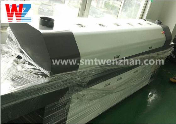
Before analyzing the complex thermodynamics of the soldering process, we must establish a clear definition of the equipment itself. This machine operates as a highly controlled heating tunnel designed specifically for mass-producing electronic assemblies.
Within a standard production line, the assembly process follows a strict and unforgiving sequence. Initially, a stencil printer applies a precise volume of paste to the bare circuit board. Next, a high-speed pick-and-place machine accurately deposits surface-mount components onto the printed pads. A high-quality PCB reflow oven machine, often configured with 8 independent heating zones for standard consumer electronics, is positioned immediately after this placement equipment.
Its primary function is to systematically heat the assembled board. The temperature must rise enough to melt the metallic alloy within the paste. This controlled melting process creates permanent, highly conductive electrical and mechanical connections. Without this specialized machinery, the mass-scale production of modern electronics would be fundamentally impossible.
The physical anatomy of a modern thermal processing system is engineered for consistency during continuous operation. The foundational components include a robust conveyor system. This is typically a mesh belt or edge-hold chain that transports the substrate through the tunnel at a strictly regulated speed. Precision heating elements generate the required thermal energy. Meanwhile, high-velocity convection fans circulate hot air or nitrogen across the board.
Furthermore, this forced convection ensures that heat is distributed evenly. It minimizes temperature discrepancies between massive processors and tiny resistors. Finally, cooling units located at the exit rapidly drop the board's temperature to solidify the molten joints.
To truly comprehend how this equipment functions, one must look beyond the basic concept of a heated box. The true working principle is based on the precise application of thermal energy over a specific duration. Process engineers call this intricate dance a thermal profile.
A thermal profile is essentially a two-dimensional graph mapping temperature on the Y-axis against time on the X-axis. As the substrate travels through the tunnel, it passes through various physical zones set to distinctly different temperatures. The speed of the conveyor combined with the temperature of each zone creates this thermal signature. The working principle is not simply about reaching the melting point of the alloy. Rather, it focuses on controlling the exact rate of heating, the duration of heat exposure, and the subsequent rate of cooling.
Looking at current industry trajectories, the push toward extreme miniaturization has made thermal profiling more unforgiving than ever. The widespread adoption of 01005 and even 008004 metric components in wearable devices requires absolute precision. Industry analysts note that modern electronics manufacturing is shifting from static profiling to dynamic, real-time thermal monitoring. Smart manufacturing and Industry 4.0 integration allow engineers to predict thermal drift before defects occur.
As high-density interconnect boards become the baseline, the margin for error in the thermal process window has shrunk to near zero. Consequently, mastering precise temperature gradients is no longer just about maximizing yield. It is a fundamental prerequisite for competing in the advanced microelectronics sector.
If the profile deviates from the optimal curve, the assembly will suffer from critical defects. Applying heat too rapidly can cause ceramic capacitors to crack. It can also cause solder to splatter across the board. Conversely, applying heat unevenly leads to the notorious tombstoning effect. This happens when small passive components stand vertically on one end due to unequal surface tension.
As the operator feeds the assembled board onto the conveyor, the preheat zone is the very first stage encountered. This initial phase sets the critical foundation for a defect-free soldering process.
The primary goal here is to safely elevate the temperature of the bare board, the delicate electronic components, and the paste from ambient room temperature to a predetermined baseline. Solder paste is a complex mixture of microscopic metal powder and chemical flux. This flux contains highly volatile solvents that make the material printable. The preheat stage must gently evaporate them.
Specifically, if these solvents are not properly burned off early on, they will boil violently in the hotter stages of the tunnel. This rapid boiling causes catastrophic blow-outs and scatters metal particles everywhere.
Industry standards dictate that the temperature ramp-up rate must be strictly controlled. The generally accepted heating slope is between 1.0 and 3.0 degrees Celsius per second. This gradual, steady incline ensures that thermal energy penetrates the component bodies evenly. It prevents internal mechanical stress from tearing the parts apart.
Deviating from this recommended heating rate introduces severe reliability risks to the final product. If the ramp rate exceeds 3.0 degrees Celsius per second, the rapid temperature change can induce thermal shock. Ceramic parts, such as Multi-Layer Ceramic Capacitors, are highly susceptible to internal micro-cracking under these conditions. On the other hand, if the heating rate is far too slow, the flux may dry out prematurely. It will lose its chemical efficacy long before the board reaches the melting phase.
Following the gentle climb of the preheat stage, the substrate enters the thermal soak zone. This phase is characterized by a much flatter temperature slope. It maintains a relatively stable heat level for a specific duration.
The soak zone serves two highly critical functions. First, it provides thermal equalization. Imagine a densely packed motherboard containing components of vastly different sizes, from tiny resistors to massive Ball Grid Array processors. Because they possess different thermal masses, they absorb heat at entirely different rates. The soak acts as a thermal buffer. It allows the temperature across the entire board to equalize perfectly.
Simultaneously, this steady heat activates the chemical flux. Once activated, the flux aggressively attacks and strips away oxidation layers from both the copper pads and the metallic component leads. Achieving clean, oxide-free surfaces is an absolute, non-negotiable requirement for the molten alloy to adhere properly.
Depending on the exact chemical formulation being used, the soak phase typically lasts between 60 to 120 seconds. During this plateau, the temperature generally ranges between 150 and 190 degrees Celsius. Process engineers must always consult the specific datasheets provided by paste manufacturers to dial in the optimal window.
In addition, a properly optimized soak zone represents your primary defense against tombstoning. By ensuring that all pads and component terminations reach the exact same temperature, the metal on both ends of a tiny resistor will melt simultaneously. This synchronized melting keeps the component perfectly flat against the board.
The reflow zone is the thermal climax of the entire operation. When peering through the viewing glass of the machine, this is the exact moment where the physical transformation occurs. The dull, sticky paste turns into a brilliant, solid electromechanical bond.
As the board advances into this zone, the temperature ramps up sharply to cross the Liquidus point. This is the specific threshold at which the alloy transitions completely into a liquid state. A critical metric monitored by engineers in this phase is the Time Above Liquidus, commonly referred to as TAL. TAL measures the exact duration the metal remains in its fluid form.
Industry guidelines generally recommend a TAL of 30 to 60 seconds. This provides just enough time for the liquid metal to react with the copper pads and form a robust Intermetallic Compound layer. If the TAL is too short, the bond will be cold and brittle. If it is too long, the intermetallic layer grows too thick, leading to long-term reliability failures.
Once liquefied, the alloy exhibits remarkable capillary action and surface tension. The molten metal flows smoothly over the flux-cleaned pads and wicks up the sides of the component leads. This dynamic process is known as wetting. Because the surface tension of the liquid metal is incredibly strong, it actively pulls slightly misaligned components into perfect registration with their pads. This highly beneficial phenomenon is known as self-alignment.
The final stage of the thermodynamic journey is the cooling zone. While occasionally overshadowed by the more dramatic heating phases, controlled cooling is equally critical for ensuring the mechanical reliability of the device.
As the assembly exits the peak heating chamber, it must be cooled efficiently to transition the liquid metal back into a solid state. This phase effectively locks the components in their final positions. It finalizes the microscopic structure of the intermetallic bond, ensuring the board can be safely handled as it moves downstream to optical inspection.
The specific rate at which the assembly cools directly impacts its internal metallurgy. The target cooling slope is typically between negative 2.0 and negative 4.0 degrees Celsius per second. Rapid, tightly controlled cooling prevents the excessive, brittle growth of the intermetallic layer.
More importantly, fast cooling forces the tin alloy to form a fine-grain crystalline structure. Joints with a fine-grain structure are visually shinier and mechanically stronger. They are highly resistant to vibration fatigue over the product's operational lifespan. In contrast, cooling the board too aggressively can induce severe thermal shock, leading to warped substrates and fractured component bodies.
For facility managers evaluating their current production lines or looking to upgrade aging infrastructure, understanding the absolute necessity of modern, compliant equipment is a critical consideration. The thermal demands of modern manufacturing have completely changed the equipment landscape.
The global electronics manufacturing industry underwent a massive transformation with the implementation of the Restriction of Hazardous Substances directive. This sweeping legislation mandated the removal of lead from commercial electronics. It forced a permanent transition from traditional tin-lead materials to environmentally friendly alternatives like the SAC305 alloy.
This metallurgical shift fundamentally changed the thermal requirements of the assembly process. Traditional materials melted at 183 degrees Celsius, allowing for a comfortable peak temperature of around 210 degrees Celsius. In contrast, SAC305 requires a peak temperature between 240 and 250 degrees Celsius to form a reliable bond.
Consequently, modern manufacturers must utilize a dedicated Lead Free reflow soldering oven designed specifically to reach and sustain these elevated temperatures. This must be achieved without compromising the structural integrity of the printed circuit board or the sensitive surface-mount devices attached to it.
Operating at higher temperatures introduces significant engineering challenges. The primary issue is the drastic narrowing of the process window. Most standard FR4 boards and plastic connectors are rated for a maximum thermal exposure of 260 degrees Celsius. With lead-free alloys requiring up to 250 degrees Celsius to melt properly, the margin for error is razor-thin.
A legacy machine with poor thermal stability might experience temperature fluctuations that easily push the board past its destruction threshold. Modern equipment mitigates this severe risk through superior thermal management. Advanced systems employ sophisticated PID controllers, high-velocity convection motors, and enhanced heavy-duty insulation. This precise engineering ensures a minimal temperature delta across the board.
Selecting the right hardware configuration involves carefully matching the machine's technical specifications to your facility's daily production volume. You must also account for the physical complexity of the boards being assembled.
When configuring a production floor, the number of independent heating zones directly dictates the resolution and flexibility of your thermal profile. An 8-zone system is generally considered the reliable baseline for standard consumer electronics. However, as board complexity increases, the thermal mass varies wildly across the surface.
For demanding applications like heavy copper backplanes or dense server boards, engineers typically specify equipment with 10, 12, or even 14 zones. For example, systems patterned after the Heller 1936 MK5 architecture utilize advanced multi-zone configurations. Additional heating modules allow for a highly granular thermal soak. This ensures that massive processors and microscopic resistors reach thermal equilibrium simultaneously.
| Feature Matrix | Standard 8-Zone Systems | Advanced 10+ Zone Systems |
|---|---|---|
| Best Application | Consumer electronics, single-layer boards | Automotive, server boards, heavy copper |
| Thermal Control Precision | Standard (Suitable for uniform thermal mass) | Extremely High (Minimizes Delta T across complex boards) |
| Conveyor Speed / Throughput | Moderate (0.6 - 0.9 meters per minute) | High (Up to 1.2+ meters per minute) |
| Lead-Free Performance | Adequate for basic SAC305 profiles | Optimized for complex, narrow-window lead-free profiles |
Manufacturers must also make a critical decision between standard atmospheric air convection and a Nitrogen-capable environment. At the extreme temperatures required for lead-free processing, the presence of atmospheric oxygen rapidly accelerates oxidation. Oxidation drastically reduces surface energy, hindering the metal's ability to flow.
By introducing Nitrogen gas into the heating chamber, oxygen is actively displaced. This inert atmosphere preserves the chemical strength of the flux and significantly improves wetting. While Nitrogen generation increases operational costs, it results in brighter, stronger joints with lower instances of internal voiding.
Finally, thermal processing equipment must never operate in isolation. It must be perfectly synchronized with upstream machinery. If the conveyor belt moves too slowly, the machine becomes a frustrating bottleneck, forcing high-speed mounters to pause. Conversely, if it moves too quickly, the substrate will not spend adequate time in each thermal zone.
Facility managers must ensure that the selected SMT line Machine Reflow Oven possesses a tunnel length sufficient to accommodate the required belt speed. A longer heating tunnel allows for a faster conveyor velocity while still maintaining the exact time-above-liquidus specified by the paste manufacturer. This ensures high throughput without sacrificing quality.
The entire soldering process relies heavily on the precise execution of four thermal stages: preheat, thermal soak, reflow, and cooling. By mastering the underlying thermodynamic principles, engineers can effectively minimize assembly defects and guarantee high-yield production runs. A meticulously crafted profile ensures that chemical fluxes activate properly and liquid alloys form reliable electromechanical connections.
Furthermore, the modern electronics landscape requires strict temperature control and advanced hardware to handle the unforgiving nature of lead-free compatibility. If you are experiencing yield issues or setting up a new facility, selecting the correct thermal processing equipment is non-negotiable. Evaluate your daily throughput, board complexity, and environmental requirements. We highly encourage manufacturers to proactively evaluate their current equipment. Visit https://www.smtwenzhan.com to explore high-performance multi-zone solutions tailored to your production needs, and secure the reliability your customers demand.
Generally, the entire process from entering the preheat zone to exiting the cooling zone takes between 4 to 6 minutes. This duration is highly dependent on the specific thermal profile required by the chemistry and the physical length of the tunnel. A standard profile typically allocates 60 to 90 seconds for preheating, 60 to 120 seconds for the thermal soak, 30 to 60 seconds for the actual melting phase, and approximately 60 seconds for controlled cooling.
Solder balling is typically caused by an excessively steep ramp-up rate during the preheat phase. If the temperature rises faster than 3.0 degrees Celsius per second, the volatile solvents trapped inside the flux flash-boil rather than evaporate gently. This violent boiling creates micro-explosions that scatter tiny metallic particles away from the pad, leaving isolated balls across the substrate surface.
Process engineers generally recommend running a profiling board through the tunnel at least once per shift or whenever changing over to a new product batch. Because thermal mass varies significantly between different board designs, a profile that works perfectly for a thin consumer gadget will fail completely on a thick server motherboard. Continuous, real-time profiling systems are now becoming the industry standard to prevent hidden thermal drift.
Not always. Older or entry-level standard machines frequently lack the heavy-duty heating capacity, thermal stability, and advanced insulation required. They struggle to reach and maintain the higher peak temperatures demanded by lead-free alloys like SAC305. Because the thermal process window for lead-free manufacturing is exceptionally narrow, using an underpowered machine can result in severe temperature gradients across the board.
While not strictly mandatory for standard consumer electronics, a Nitrogen environment is highly recommended for complex lead-free assemblies, fine-pitch micro-components, or high-reliability aerospace boards. Nitrogen displaces atmospheric oxygen inside the heating chamber. This drastically reduces the rapid oxidation of the molten alloy and the copper pads, leading to superior wetting and stronger intermetallic bonds.