Views: 0 Author: Site Editor Publish Time: 2026-10-06 Origin: Site
Modern electronics manufacturing leaves absolute zero room for error. A single misaligned component quickly ruins production yields, turning a profitable run into a costly scrap heap. Surface mount technology operates at blistering speeds. Therefore, assuming your equipment is hitting the mark is a dangerous gamble. You need empirical, statistical proof of exact machine precision.
This is where CPK, known as the Process Capability Index, becomes the golden standard for quality assurance. It statistically proves that your equipment can consistently place microscopic components—like 01005 passives or fine-pitch BGAs—within strict tolerance limits. Whether you are operating a standard assembly line or a specialized Automatic LED Pick And Place Machine, running a proper test is essential for reducing rework and maximizing yield.
Looking at the current trajectory of the SMT sector, the push toward hyper-miniaturization is relentless. With the widespread adoption of 008004 micro-components and ultra-dense electric vehicle control boards, the margin for error has shrunk from millimeters to mere microns. Contract manufacturers face stricter entry barriers today. Top-tier OEMs no longer view capability reports as optional quality assurance steps. If a facility cannot provide real-time, passing statistical data, they simply will not win bids for high-reliability aerospace, medical, or automotive contracts. Precision is a strict baseline requirement.
In the realm of surface mount technology, speed means nothing without precision. The capability index is a statistical measurement demonstrating how close a manufacturing process is to its specification limits. It also reveals how consistent that process remains over time.
Applied specifically to factory environments, it measures the exact deviation of component placement from the absolute theoretical center of the PCB pad. It evaluates this deviation across the X-axis, the Y-axis, and the rotational angle. By calculating the standard deviation of these placements, engineers mathematically prove whether a machine handles ultra-fine pitch components without exceeding allowable tolerances.
While often used interchangeably on the factory floor, CP and CPK measure two distinctly different aspects of machine performance. Grasping this distinction is fundamental to diagnosing placement errors.
CP measures the spread or variation of the placements. It answers a simple question: can the machine group all its placements tightly together? A high CP means the machine is highly precise and repeatable. However, it completely ignores the target center. A machine could have an excellent CP score while placing every single component precisely 0.5mm off-center into empty space.
In contrast, CPK measures both the spread and how centered those placements are relative to the intended target. It combines precision with accuracy. A high score guarantees that placements are tightly grouped and land perfectly in the center of the pad.
| Feature | CP - Process Capability | CPK - Process Capability Index |
|---|---|---|
| Core Focus | Spread and variation only. | Centering and variation combined. |
| Target Pad Alignment | Ignores the actual target center. | Evaluates distance to the absolute target center. |
| High Score Meaning | Placements are tightly grouped together. | Placements are tightly grouped AND perfectly centered. |
| Production Risk | High risk. Tight grouping might be entirely off-pad. | Low risk. Guarantees reliable reflow soldering. |
The financial impact of poor placement accuracy extends far beyond the mounter itself. When an SMD SMT Pick And Place Machine drops a component slightly off-center, operators often hope the surface tension of the molten solder will pull it back into alignment during reflow. This is a dangerous assumption.
Mechanical deviation directly leads to severe manufacturing defects. These include tombstoning, solder bridging, and entirely skewed components. According to the industry-standard Rule of 10, the cost to identify and repair a defect increases tenfold at each subsequent stage of production. Catching a calibration error at the machine level costs cents. Repairing a bridged BGA after reflow soldering—or worse, handling a warranty claim after the product reaches the consumer—costs thousands of dollars and permanently damages brand reputation.
Subjective claims of "good enough" accuracy are insufficient for modern production. The IPC-9850 standard defines exact methodologies for evaluating placement performance. It outlines specific test materials, environmental conditions, and statistical formulas required to verify equipment capability objectively.
Conducting a valid test requires eliminating external variables. Imagine trying to test micron-level accuracy on a standard FR4 board that has warped by 0.2mm due to humidity. Your data would be instantly corrupted. If the test materials are flawed, the resulting data is entirely invalid.
Standard printed circuit boards are susceptible to thermal expansion and manufacturing tolerances. To isolate the machine's true mechanical accuracy from board defects, utilize a specialized glass grid board. Glass provides exceptional thermal and dimensional stability.
Once a component is placed, it must stay exactly where the nozzle deposited it during transit to the measurement equipment. Use highly uniform double-sided tape or a precisely controlled application of tacky flux to lock the dummy components in place. Standardized, perfectly manufactured dummy chips feature strict dimensional tolerances. This ensures physical variations in the chips themselves do not skew the vision system's data.
The naked eye cannot measure deviations at the micron level. To capture precise coordinates, specialized metrology equipment is mandatory. Engineers typically rely on a Coordinate Measuring Machine or a high-precision Automated Optical Inspection system. The tool scans the glass board, identifies the exact physical center of every placed component, and compares those coordinates against theoretical CAD data.
A frequent mistake in testing is evaluating a cold machine. Every mounter utilizes linear encoders, ball screws, and servo motors that generate heat during operation. This heat causes microscopic thermal expansion in the metal frame and drive mechanisms.
To capture real-world production accuracy, the equipment must undergo a standard warm-up routine. Allow the placement heads to move through their full range of motion for 30 minutes. This ensures all mechanical components, lubricants, and drive belts reach normal operating temperatures, stabilizing chassis dimensions before the test begins.
The test program must intentionally challenge the machine across its entire placement area. Program a specific matrix pattern that spans the full dimensions of the glass test board.
A rigorous program utilizes every available nozzle and placement head. Furthermore, instruct the machine to place components at various rotational angles, typically 0, 90, 180, and 270 degrees. Testing multiple angles ensures that rotation motors and vision system algorithms function flawlessly across all orientations.
With the warm-up complete, execute the placement run. Statistical validity relies heavily on sample size. Running a test with only five components yields mathematically unsound scores.
Industry best practices dictate a minimum of 30 to 50 placements per nozzle. If your machine features an 8-head configuration, the test run should consist of at least 240 total placements. This statistically significant sample size smooths out anomalous data points.
Once the placement cycle concludes, carefully remove the glass test board from the conveyor. Aggressive handling shifts components, forcing a complete restart.
Transfer the board to the measurement system. The metrology software scans the board, locates fiducial marks to establish a baseline coordinate system, and measures the exact center and rotation of every single dummy component. The system then generates a raw data set of X, Y, and Theta errors.
While modern metrology software automatically crunches the numbers, understanding the underlying math empowers process engineers to make better decisions. The formula calculates the distance from the mean placement position to both the upper and lower specification limits, divided by three times the standard deviation.
The formula generates two values. The final score is the lower of these two values, representing the worst-case scenario for your process capability.
Interpreting the final score dictates your necessary operational response. The benchmarks are strictly defined across the industry.
A score below 1.0 means the process is poor and not capable. Variation exceeds specification limits. Halt production immediately, as major calibration or mechanical repair is required. A score between 1.0 and 1.33 is acceptable but lacks a safety margin. Proceed with caution and monitor defect rates closely. A score above 1.33 is the recognized industry standard for good capability, providing a safe statistical buffer for mass production. Finally, a score above 1.67 represents Six Sigma quality, where defect probability is statistically near zero.
When your calculated score falls below 1.33, it indicates your process is drifting off-center or suffering from excessive variation. Because these mounters are complex mechatronic systems, diagnosing the issue requires a structured approach like the 5M1E model—Man, Machine, Material, Method, Measurement, and Environment.
Specifically, mechanical degradation within the "Machine" category is the most common culprit. Worn-out nozzles, stretched drive belts, or uncalibrated servo motors directly degrade repeatability. If Z-axis dampening springs fail, the nozzle strikes the board too hard, causing the component to slide upon impact.
Addressing a low score requires precise interventions. Execute a comprehensive cleaning of all optical components, including upward-looking cameras and nozzle reflectors. Replace deformed vacuum nozzles immediately. Verify the tension of the X and Y axis belts using a sonic tension meter.
If routine maintenance fails to improve your score, your equipment may have reached the end of its mechanical lifespan. This is exactly where strategic equipment selection becomes critical. Modern solutions are engineered to prevent these exact mechanical drifts. For example, upgrading to a highly stable SMT Pick And Place Machine like the BM123 or BM221 series provides superior gantry stability. These systems feature advanced linear guide rails and optimized Z-axis dampening that eliminate impact sliding.
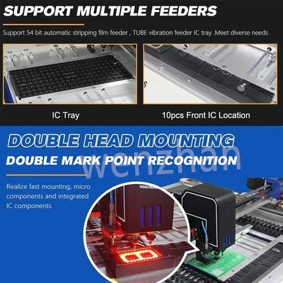
In addition, if you are assembling specialized LED panels, utilizing a 2-head high-drive mini desktop mounter ensures placement heads maintain strict Theta accuracy even at maximum speeds. Features like dual-head simultaneous pickup and integrated vision centering eliminate the rotational errors that plague older pneumatic machines.
Achieving a passing score during validation is only the first step. The true challenge lies in sustaining that precision across millions of cycles. Long-term accuracy requires shifting from reactive troubleshooting to proactive, data-driven maintenance.
Preventive maintenance is the absolute foundation of mechanical repeatability. On a daily basis, operators must inspect and clean all active nozzles using approved solvents. The machine’s incoming compressed air pressure must be verified, as fluctuating pressure directly impacts vacuum generation and stable component pickup.
Weekly protocols require deeper inspection. Technicians should clean camera lenses to ensure high-contrast images and wipe down linear guide rails to maintain adequate lubrication. Monthly tasks involve checking drive belt tension and replacing clogged vacuum filters, which delay the release of components during placement.
Furthermore, verification should not be treated as a one-time commissioning event. Run a full test annually or semi-annually based on production volume. This creates a historical baseline, allowing engineers to track gradual mechanical degradation over years of service. Beyond scheduled intervals, run an immediate test after any physical collision or major component replacement.
Establish a baseline by running a full test annually or semi-annually as part of your standard preventive maintenance program. However, you must also run an immediate test after any major machine collision, after relocating the equipment on the factory floor, or following the replacement of critical mechanical components like servo motors. Frequent testing ensures minor mechanical drifts are caught before they cause defects.
Yes, placement speed significantly impacts the resulting score. Operating a machine at its absolute maximum theoretical speed often induces chassis vibrations that mechanical dampening systems cannot fully absorb. This causes micro-shifts upon component release. To obtain actionable data, IPC-9850 standards mandate testing machines at sustainable, real-world production speeds.
Absolutely. The tape feeder is a critical mechanical extension of the placement process. If a feeder's internal gears are worn, it vibrates excessively or fails to advance the tape smoothly. The component rests off-center inside the pocket. This forces the placement head to make large, rapid corrections, leading to poor vacuum seals and rotational errors that directly degrade accuracy.
Placement accuracy refers to how close a placed component is to the exact theoretical center of the target pad. Repeatability measures how consistently the machine places the component in the exact same spot across multiple attempts, even if that spot is off-center. A high capability score requires both. The machine must place components tightly together directly on the target center.
Automotive standards are significantly stricter than general consumer electronics. While a score of 1.33 is acceptable for standard goods, automotive contract manufacturers typically require a minimum score of 1.67. This Six Sigma quality level ensures near-zero defect rates, which is critical for high-reliability, safety-related vehicle control boards.
A chipped or deformed vacuum nozzle fails to hold the component perfectly flat during transit. When the upward-looking vision system scans a tilted component, it calculates an incorrect center point. This introduces severe X, Y, and rotation errors upon placement, instantly tanking your statistical score regardless of how well the gantry operates.
Running this statistical test verifies your machine's core health. It is not just a theoretical math exercise; it is a critical diagnostic tool. Accurate data prevents costly errors on the production floor, protecting both your profit margins and your customers' trust. Reliable, well-calibrated equipment ensures your production stays efficient.
If your current assembly line struggles to maintain a score above 1.33, it is time to evaluate your hardware capabilities. Visit https://www.smtwenzhan.com to explore high-precision automated mounters, from low-cost PCB production machines to advanced dual-head LED placement systems. Contact our engineering team today for expert assistance with setup, calibration, and continuous yield improvement.