Views: 0 Author: Site Editor Publish Time: 2026-10-03 Origin: Site
Bad oven settings ruin perfect PCB prints. You can execute flawless solder paste printing. You can achieve micron-level component placement. Yet, a single improper thermal setting undoes all that hard work instantly. Mastering your reflow process stops these costly assembly errors dead in their tracks.
At the core of modern electronics manufacturing, the reflow system dictates final yield. Are you running a massive continuous production line? Or perhaps utilizing a space-saving equipment layout? The fundamental principles of machine management remain identical. We will walk through the critical steps of line setup, precise profile checks, daily operation tips, and essential troubleshooting from a floor engineer's perspective.
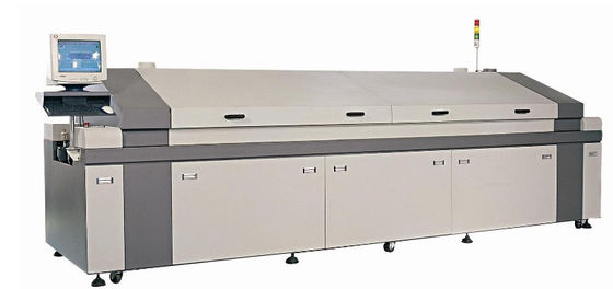
At its essence, an SMT reflow system executes a highly controlled thermal cycle. It applies precise convective heat to a printed circuit board. This melts the deposited solder paste, forming permanent electrical and mechanical connections between surface-mount components and the board's copper pads. Apply heat too violently? Sensitive electronic packages crack from thermal shock. Proper operation dictates that this heating process must be gradual and uniform.
To achieve this delicate balance, the internal chamber features multiple independent heating zones. We universally categorize the entire reflow process into four critical stages. Understanding these stages is the absolute foundation of effective machine management.
Before initiating any thermal profiling or production runs, you must meticulously verify the physical and systemic setup. Proper installation directly impacts thermal stability and operator safety on the factory floor.
Physical Placement and Environment
When configuring an SMT oven reflow solder machine, physical placement is your first priority. The oven must be perfectly leveled on a vibration-free surface. Adequate clearance around the machine is mandatory for maintenance access, particularly near the electrical panels and flux management systems. Furthermore, robust exhaust ventilation is not optional. Reflow processing generates volatile organic compounds and harmful flux fumes. Your facility's exhaust extraction system must meet specific cubic feet per minute requirements to pull these fumes away safely, preventing sticky residue buildup inside the heating chambers.
Industry Trend Analysis: The Shift to Smart Connectivity
The electronics manufacturing sector is rapidly shifting toward Industry 4.0 integration. Modern line setups now heavily emphasize smart factory connectivity. Instead of operating as isolated islands, today's reflow machines continuously communicate with upstream pick-and-place systems and downstream automated optical inspection machines. Utilizing SMEMA or Hermes protocols allows automated conveyor speed adjustments. This prevents board bottlenecks and optimizes throughput based on real-time data. We also see a surge in AI-assisted thermal profiling, where software predicts zone adjustments before thermal drift causes actual defects.
Hardware and Software Initialization
The daily power-on sequence should follow strict standard operating procedures. After engaging the main breaker, the software interface must boot fully to verify seamless communication with the programmable logic controller. Operators should physically test all emergency stop buttons and safety interlocks on the hood panels to ensure they are fully functional before a single board enters the tunnel.
Conveyor System Calibration
Accurate conveyor setup prevents catastrophic board drops or mechanical jams. Adjust the mesh belt or edge pin conveyor width to match the specific PCB size, leaving a tiny 1 to 2mm clearance. This gap accommodates the natural thermal expansion of the FR4 material as it heats up. Setting the initial conveyor speed is equally critical, as the belt velocity directly dictates the dwell time the assembly spends in each specific temperature zone.
Guessing temperature setpoints guarantees manufacturing failure. A precise thermal profile serves as your process blueprint. Get it wrong, and you will inevitably experience scorched boards, thermally damaged microchips, or weak solder joints that fail in the field.
Setting Up the Profiler
A thermal profiler is a specialized data-logging device that travels through the heating tunnel alongside the PCB. Technicians attach fine-gauge thermocouples to a dummy test board using high-temperature solder or specialized Kapton tape. Place these strategically: one on the largest component, one on the smallest component, one on the bare FR4 substrate, and one near the leading edge. This specific distribution captures the temperature differential across the entire complex assembly.
Adjusting for RoHS Compliance
The global transition from tin-lead to lead-free solder pastes fundamentally altered profiling requirements. Operating a modern lead free SMT reflow oven requires significantly higher peak temperatures. You typically need between 240 and 260 degrees Celsius to achieve a proper liquid state. These aggressive temperatures sit perilously close to the maximum thermal tolerance of many plastic electronic packages. Therefore, the process window is exceptionally tight. Upgraded internal insulation and highly precise forced-air convection blowers are standard in these 8-zone and 10-zone machines to meet strict environmental compliance without causing thermal degradation to the product.
Analyzing the Profiling Data
Once the profiler exits the cooling zone, the software generates a detailed time-versus-temperature curve. Process engineers must analyze this raw data against the solder paste manufacturer's exact specifications. If the Time Above Liquidus is too short, you may need to decrease the conveyor speed or slightly increase the reflow zone temperatures. In contrast, if the ramp rate in the initial preheat zone exceeds 3 degrees Celsius per second, you must lower those early zone temperatures to prevent the paste solvents from boiling abruptly and causing solder splatter.
Achieving consistent yield requires a highly disciplined approach to daily operation. Treating this complex thermal equipment as a set-and-forget tool inevitably leads to process drift and severe quality degradation.
Pre-Shift Inspection and Warm-Up
Execute a standard pre-shift checklist before running any production batches. Listen for the hiss of the nitrogen valves and check the parts-per-million oxygen levels on the monitor if the process requires an inert atmosphere. Verify the exhaust flow sensors. Clear any leftover debris or dropped components from the mesh belt. After powering on the heaters, a robust 4800W machine requires 15 to 30 minutes to reach true thermal equilibrium. Rushing to run boards before the software indicates a stable ready state results in under-processed cold joints.
Running the First Article Inspection
Once temperatures stabilize, send the first assembled board of the batch through. Subject this board to rigorous visual and Automated Optical Inspection. Quality control technicians verify that solder fillets are smooth and concave. They ensure components are perfectly aligned and absolutely no bridging or voiding has occurred. Full-scale production should only commence after this inspection is officially approved and documented.
Continuous Production Monitoring
During high-volume runs, the thermal load inside the chamber increases as cold boards continuously enter. Operators must keep a watchful eye on the software dashboard for any sudden temperature drops in the reflow zones or unexpected conveyor speed fluctuations. Modern PID controllers rapidly compensate for heavy board loading. However, human oversight remains essential to catch subtle anomalies before they ruin an entire batch.
Safe Shutdown Procedures
Never simply cut the main power breaker at the end of a shift. These machines contain massive amounts of retained heat. Place the system into an automated cool-down cycle. This crucial sequence keeps the conveyor running and the blower motors active until the internal chamber temperature drops below a safe 100 degrees Celsius. Cutting power prematurely traps the heat, which can warp the internal metal chassis and permanently fry the blower motor bearings.
Modern electronics manufacturing increasingly demands flexibility. Facilities are rapidly transitioning from traditional high-volume environments to high-mix low-volume production models. Product changeovers happen more frequently, making equipment footprint and operational agility paramount. How do you choose the right configuration for your factory floor?
Space-Saving vs. Heavy-Duty Performance
Historically, achieving exceptional thermal stability required massive sprawling ovens with 10 or 12 heating zones. Today, advanced aerodynamic engineering allows a slim SMT reflow oven equipped with integrated thermal profiling software to deliver comparable top-tier thermal performance in a significantly reduced footprint. These compact profile ovens utilize high-efficiency heating elements and optimized airflow designs. By increasing the velocity of the convection impellers, they transfer heat to the PCB highly effectively, maintaining a tight temperature differential across complex multi-layer boards without eating up valuable factory floor space.
Conversely, if you are running continuous high-mass automotive boards or telecom backplanes, an 8-zone or 10-zone heavy-duty industrial system provides the extended soak times required to penetrate massive thermal loads.
Core Comparison: Slim Profile vs. Standard Multi-Zone Ovens
| Feature | Slim Profile Reflow Oven | 8 to 10 Zone Industrial Oven |
|---|---|---|
| Factory Footprint | Highly compact, ideal for crowded floors. | Large footprint, requires dedicated line space. |
| Ideal Production Type | High-mix low-volume, frequent changeovers. | High-volume continuous runs, heavy thermal mass. |
| Power Consumption | Optimized efficiency, lower baseline draw. | Higher draw, typically 4800W+ during ramp-up. |
| Thermal Stability | Excellent for standard consumer electronics. | Unmatched for thick copper and multi-layer boards. |
Energy Efficiency and Quick Changeovers
Proper operation in modern machines drastically reduces facility overhead. Utilizing automated standby modes during production pauses drops zone temperatures by a safe margin, significantly cutting electricity and nitrogen consumption. To expedite changeovers, smart production schedules group boards with similar thermal mass requirements consecutively. Remember that it is always faster for the heaters to ramp up than to cool down. Scheduling lower-temperature profiles before higher-temperature ones saves hours of idle production time every week.
Even with a flawless setup, variables in bare PCB fabrication, component lead plating, or solder paste handling introduce frustrating defects. Troubleshooting requires a systematic approach. You must map the visual defect directly to the specific zone in the thermal profile.
| Solder Defect | Visual Characteristics | Common Root Cause | Recommended Profile Adjustment |
|---|---|---|---|
| Tombstoning | Small passive components such as 0402 resistors stand vertically on one end. | Uneven heating causing solder on one pad to melt faster than the other. Excessive ramp-up rates. | Lengthen the thermal soak zone to ensure both pads reach equilibrium. Reduce the ramp rate in the preheat zone. |
| Cold Solder Joints | Dull, grainy, or irregular solder connections with poor pad wetting. | Peak temperature is too low, or Time Above Liquidus is too short. | Increase the temperature setpoints in the reflow zones, or slightly decrease the conveyor speed. |
| Delamination / Blistering | Bubbles or separation within the layers of the FR4 PCB substrate. | Moisture trapped inside the PCB rapidly expanding, or peak temperature is excessively high. | Pre-bake the bare PCBs in a separate drying oven. Lower the peak temperature in the reflow zone. |
| Solder Balling | Tiny, isolated spheres of solder scattered around the component pads. | Rapid outgassing of flux due to heating too quickly, causing paste splatter. | Decrease the ramp-up rate in the preheat zone to allow solvents to evaporate more gently. |
Proper operation extends far beyond simply setting the correct thermal profile. It demands a rigorous, well-documented, and consistently executed maintenance schedule. Lead-free solder pastes contain highly active fluxes that vaporize intensely during the heating process. If these volatile flux residues are not properly managed, they inevitably condense on internal cooling radiators, exhaust pipes, and sensitive temperature sensors. Over time, this buildup leads to severe thermal instability, increased power consumption, and critical soldering defects.
Before performing any maintenance, operators must strictly adhere to Lockout Tagout safety procedures to ensure the machine is fully depowered and cooled to a safe handling temperature.
Daily Maintenance Procedures
Daily tasks focus on rapid visual inspections and basic surface cleaning to prevent immediate mechanical jams during a shift.
Weekly and Monthly Maintenance Procedures
Weekly and monthly tasks are significantly more intensive. They require the machine to be temporarily shut down to safely access internal filtration and drive components.
Mastering reflow oven operation is a delicate blend of accurate physical setup, precise empirical thermal profiling, and highly diligent daily maintenance. Guesswork has no place on the modern SMT floor. Consistent thermal profiling effectively prevents costly manufacturing defects, while routine upkeep keeps your equipment running smoothly without unexpected expensive downtime.
Whether you are operating a massive multi-zone industrial unit or a highly efficient space-saving slim model, taking the time to verify the profile and perform daily checks results in near-zero defect manufacturing. This dedication to process control provides a massive boost to your bottom line. Are you ready to eliminate soldering defects and upgrade your assembly line? Evaluate your current thermal profiles today. For facilities looking to enhance their production yield with high-performance thermal solutions, discover our complete range of advanced reflow systems at https://www.smtwenzhan.com to find the perfect match for your smart factory setup.
It is highly recommended to run a comprehensive thermal profile check every time you introduce a new PCB design, change solder paste formulations, or after performing any major machine maintenance such as replacing a blower motor. Because different components absorb heat at drastically different rates, a profile for a lightweight board will fail on a heavy multi-layer board. For continuous high-volume production of the exact same product, performing a profile verification once a week is considered a standard best practice in the industry.
A lead-free oven is specifically engineered from the ground up to handle the significantly higher thermal demands of RoHS-compliant manufacturing. Traditional leaded solder melts at approximately 183 degrees Celsius, whereas common lead-free alloys require temperatures around 217 to 220 degrees Celsius to reach a liquid state. Consequently, a lead-free oven features upgraded high-efficiency heating elements, superior internal thermal insulation, and advanced forced-air cooling zones to sustain peak temperatures of up to 260 degrees Celsius without warping the chassis. They also incorporate much more aggressive flux management systems.
Yes. Modern slim profile ovens are fully capable of processing complex heavy-copper and multi-layer printed circuit boards. The primary difference is the physical length of the heating tunnel and footprint, not the fundamental quality of thermal transfer. Slim ovens utilize advanced forced-air convection technology and optimized internal airflow dynamics to achieve rapid stable heat transfer. As long as the thermal profile is calibrated correctly, a slim oven delivers the exact same flawless solder joints as a larger unit.
A minimal amount of exhaust vapor near the entrance and exit tunnels is normal as the chemical flux vaporizes. However, excessive thick smoke indicates a significant issue. The most common cause is a severely clogged flux management system or a saturated filtration mesh, forcing vaporized flux into the ambient factory environment. Another potential cause is inadequate facility exhaust ventilation, meaning the external extraction fans are not pulling enough air. Finally, a heavily contaminated conveyor belt covered in burned residue can also generate noticeable smoke.
Conveyor speed is one of the most critical variables, as it directly dictates the exact amount of time the PCB spends in each temperature zone. If the conveyor moves too quickly, the board will not absorb enough heat, leading to unactivated flux and cold brittle solder joints. Conversely, if set too slowly, the PCB remains in the high-temperature zone for an extended period. This excessive heat exposure makes the intermetallic layer overly thick and fragile, thermally damages sensitive plastic components, and can cause the fiberglass substrate to warp or delaminate.
The earliest and most obvious sign of a failing or clogged system is an unusual accumulation of sticky amber-colored residue on the cooling zone panels and the exit conveyor rails. You may also notice a distinct increase in acrid chemical odors or visible smoke lingering around the machine casing. In severe cases of neglect, condensed liquid flux can literally drip from the ceiling of the cooling zones directly onto the freshly soldered PCBs passing below, causing critical cosmetic and functional defects.
Time Above Liquidus refers to the specific duration that the solder paste remains in a fully liquid molten state during the peak heating phase. For most standard lead-free alloys, the optimal duration is typically maintained between 45 and 90 seconds. Maintaining the correct time is absolutely critical for forming a strong metallurgical bond. If it is too short, the solder will not properly wet the pad. If it is too long, the intermetallic compound layer becomes excessively thick, rendering the joint brittle and prone to cracking during thermal cycling.
There is no single universal conveyor speed, as the ideal setting is entirely dependent on the length of your oven's heating tunnel and the specific thermal mass of your PCB assembly. Typically, speeds range from 60 to 120 centimeters per minute. The goal is to set a speed that allows the board to hit every targeted temperature milestone defined by your solder paste manufacturer. A longer 10-zone oven can run at higher conveyor speeds while still providing adequate soak time, whereas a compact oven requires a slower speed to achieve the same thermal transfer.
Proper measurement requires passing a dedicated thermal profiling unit through the oven alongside a test board. You must attach high-temperature thermocouples directly to critical areas of the PCB using specialized tape or high-temp solder. Always place sensors on the component with the highest thermal mass, the component with the lowest thermal mass, and directly on the bare board substrate. As the profiler travels through the tunnel, it records the exact temperature at these points every fraction of a second, generating a comprehensive curve that you can analyze against your process limits.