Views: 0 Author: Site Editor Publish Time: 2026-10-20 Origin: Site
In the fast-paced world of electronics manufacturing, seamless board handling acts as the backbone of an efficient Surface Mount Technology line. Picture the factory floor: pick-and-place machines humming and stencils printing perfectly, yet a sudden bottleneck occurs simply because a board fails to fit the transport track. A critical, albeit frequently overlooked, specification when setting up or upgrading a production line is the dimensional capacity of your handling equipment. Choosing the precise size ensures your line can gracefully process everything from tiny wearable tech circuits to massive LED display panels without jamming or dropping. This guide breaks down standard dimensional ranges, the mechanics behind rail adjustments, and how specialized equipment optimizes your daily workflow.
When evaluating transport modules for an assembly line, you will quickly discover that most machines are adaptable to accommodate diverse board dimensions. However, they operate within strict mechanical boundaries dictated by their chassis design and rail engineering.
Across the electronics manufacturing sector, the universally accepted minimum width limit for standard edge-handling conveyors sits at 50mm. You might wonder why this threshold exists. Substrates smaller than 50mm lack the necessary mass and surface area to remain stable while transitioning across belts. Furthermore, standard edge clearance requires 3mm to 5mm on each side for the transport mechanism to grip the board securely. When manufacturers process micro-circuits for medical implants or compact sensors, they typically use multi-board panels to ensure stable transit through the reflow oven.
On the opposite end of the spectrum, maximum capacities are categorized based on the footprint of the SMT line and the target industry. Compact conveyors for consumer electronics usually max out between 250mm and 330mm. For heavy-duty production involving server backplanes or automotive controllers, conveyors expand to support widths of 390mm or 460mm. In the telecommunications and lighting sectors, the demand for exceptionally long and wide substrates has pushed the industry toward specialized systems. These can support widths of 500mm to 1200mm, often requiring reinforced center-support mechanisms to prevent wide boards from sagging under their own weight.
Modern electronics assembly rarely involves running the same board continuously throughout the year. The industry has shifted toward high-mix, low-volume production models, where the ability to adjust conveyor widths rapidly acts as a driver of operational efficiency.
The speed at which a team modifies rail width dictates the transition time between product batches. When capital-intensive machines sit idle while waiting for tracks to be resized, the factory loses potential output. Efficient adjustability minimizes this idle time, maximizing the overall equipment effectiveness of the entire floor.
The physics of board handling demand absolute precision. If rails are set even a millimeter too wide, the board risks slipping off the transport belts, resulting in scrapped assemblies. Conversely, if adjusted too tightly, lateral compression forces the PCB to bow upward in the center. This bowing alters the focal height for automated optical inspection cameras and can cause severe mechanical jams within the machine chassis.
Current trends show a polarization in board sizes. Consumer wearables push the limits of miniaturization, demanding highly stable panelized processing. Simultaneously, the growth of the electric vehicle market and 5G infrastructure requires unusually large, heavy substrates. Consequently, the market is seeing a surge in demand for heavy-duty conveyors capable of handling widths exceeding 500mm while supporting heavy payloads. Facilities are increasingly moving away from bare-minimum specifications, opting for robust, automated handling systems to future-proof their lines.
The engineering method utilized to alter the span of the conveyor rails impacts both handling accuracy and floor efficiency. Manufacturers typically choose between two primary mechanisms based on their operational tempo.
Manual systems rely on mechanical lead screws connected to a hand crank at the machine's edge. An operator physically turns the wheel to move the mobile rail. While this is cost-effective, it remains prone to human error. Technicians may inadvertently over-tighten rails or fail to ensure they are perfectly parallel, leading to the bowing issues noted earlier.
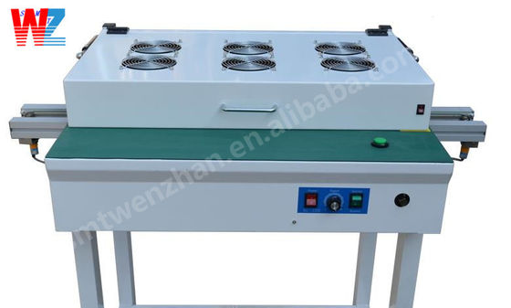
To eliminate human error and accelerate changeovers, contemporary lines often utilize a full automatic pcb conveyor. These systems replace cranks with precision stepper motors and programmable logic controllers. Engineers save exact width dimensions as software recipes. When a new batch begins, the operator scans a product barcode, and the machine automatically drives the motors to resize the rails to the exact millimeter, achieving perfect tension in seconds.
While standard modules transport boards horizontally, modern lines incorporate specialty handling equipment to execute complex physical maneuvers that demand stricter dimensional tolerances.
Double-sided assembly requires boards to be inverted after the first side passes through the reflow oven. A PCB Conveyor SMT Flipper Machine is specifically engineered to receive, secure, and rotate a board exactly 180 degrees. Because the board is lifted against gravity, standard belt tension is insufficient. Width adjustment on a flipper must be precise, often utilizing secondary pneumatic clamps to grip the edge clearance without crushing delicate components.
Buffer conveyors act as cooling or storage stations using vertical rack systems. The adjustment mechanism must maintain flawless parallel alignment across the height of the rack. If rails taper even slightly, a board entering a higher slot will inevitably jam, bringing the entire line to a halt.
The construction materials of the rails and lead screws dictate the machine's ability to maintain a consistent width over thousands of hours of operation. As PCBs grow larger and carry heavier components, the weight exerted on the transport belts increases.
Standard aluminum rails can micro-flex under extreme payloads. In contrast, an SS smt conveyor utilizes rigid stainless steel rails that maintain absolute straightness, ensuring uniform width from entrance to exit. Furthermore, stainless steel prevents lead screws from oxidizing in humid factory environments. This wear resistance ensures mechanical movements remain smooth, preventing motors from stalling or cranks from seizing over the equipment’s lifespan.
Procuring new handling equipment is a long-term investment. Production managers must look beyond current needs. Consult with R&D teams to map out designs for the next few years. If prototyping involves massive LED arrays, purchasing a standard 330mm conveyor today creates a bottleneck tomorrow. Ensure that the new module’s fixed rail aligns with existing equipment and that it supports standard communication protocols, allowing the line to resize itself synchronously.
Even with premium modules, operators must maintain mechanical calibration to prevent bottlenecks. If boards get stuck in the middle, it is almost exclusively caused by a loss of rail parallelism. Use digital calipers to measure inner edges at the entrance, center, and exit; realign guide blocks until these points are identical within a tight tolerance. If boards fall off, the span is likely set too wide. Implement a protocol using a dummy board of exact dimensions to set the tension before locking the rail. Should adjustments become stiff or noisy, apply an industrial degreaser to the lead screws, followed by a fresh coat of synthetic lithium lubricant.
Understanding the precise width range a PCB conveyor supports is fundamental to building a high-yielding SMT line. Whether processing standard 50mm multi-board panels or massive 460mm industrial substrates, selecting the correct dimensional capacity ensures safe transit. By investing in robust materials like stainless steel and leveraging automated systems, manufacturers can slash downtime. Always evaluate your long-term production roadmap to ensure your handling equipment scales alongside your business.
The industry standard for the minimum width capacity of a conventional SMT conveyor is 50mm. Boards smaller than this lack the surface area required for stable transport and edge gripping. Consequently, designs requiring smaller footprints are panelized into larger arrays to meet this minimum requirement.
Yes, modern manufacturing relies on automated width adjustment to facilitate high-mix production. Automated systems replace manual hand-cranks with stepper motors and controllers. Operators select a pre-programmed recipe, prompting the machine to resize its rails to the exact millimeter, which eliminates human error.
A flipper machine performs an inversion maneuver that requires extreme precision. When the board enters, a pneumatic or motorized clamping mechanism descends, applying regulated pressure to the outer edge clearance zone. This ensures the board does not slip or drop during the 180-degree rotation while protecting delicate components.
Stainless steel offers exceptional rigidity and high tensile strength compared to aluminum. It does not bow outward under heavy payloads, and it resists corrosion, which ensures that the intricate threads of the width-adjusting lead screws remain smooth over years of heavy operation.
The maximum capacity depends on the structural classification of the equipment. Compact conveyors for consumer electronics typically max out between 250mm and 330mm, while standard full-size systems support widths up to 460mm. Specialized equipment for the lighting and telecommunications industries can feature extended capacities reaching 1200mm.