Views: 0 Author: Site Editor Publish Time: 2026-10-18 Origin: Site
Walk onto any modern electronics assembly floor, and you will notice a stark reality. Components are shrinking, and processing power is exploding. Ball Grid Array packages have naturally become the standard for high-density printed circuit boards. Unlike older packaging types, these components deliver superior thermal dissipation and higher pin counts within a remarkably compact footprint.
However, this architectural innovation introduces a formidable production hurdle. Imagine an operator inspecting a newly populated board on the line. With older gull-wing integrated circuits, a quick visual pass reveals whether a lead is bent or misaligned. With bottom-terminated components, that same operator sees nothing but the opaque top of a resin square. Because the critical solder joints reside entirely underneath the component body, visual inspection post-placement is nearly impossible without costly, specialized X-ray equipment. Any deviation requires complex rework stations, localized heating, and significant downtime. Therefore, achieving mathematical perfection on the very first placement attempt is not just a goal, but an absolute necessity for maintaining profitable yields.
Fixing this bottleneck requires highly specialized assembly equipment. This guide breaks down the exact empirical accuracy specifications required for flawless placement. We will explore the underlying optical and mechanical technologies that make micron-level precision a reality, providing actionable insights for process engineers looking to upgrade their surface-mount assembly lines.
Before diving into the mechanical tolerances, we must look at where the manufacturing sector is heading. Recent industry data shows a massive shift toward ultra-high-density interconnect boards. This surge is heavily driven by 5G telecommunications infrastructure, advanced automotive driver-assistance systems, and wearable smart devices.
Consequently, assembly facilities are routinely tasked with processing microscopic component pitches. Layouts that were considered strictly experimental just half a decade ago are now daily production targets. This paradigm shift means older placement technologies are rapidly becoming obsolete. Manufacturers are practically forced to upgrade their capital equipment simply to maintain viable first-pass yields on modern consumer electronics.
To truly understand the stringent requirements placed on modern assembly equipment, one must first recognize how fundamentally different these packages are from standard surface mount devices. Traditional components like chip resistors or standard integrated circuits feature visible metallic leads extending from their perimeter. This fundamental design difference drastically alters the operational requirements for the machinery handling them.
Because the conductive leads are concealed beneath the package, the mounting system is flying blind if it relies on outdated alignment methods. If a standard chip is placed slightly off-center, the surface tension of the molten solder during reflow might self-align the lightweight component. High-density arrays are far less forgiving. The equipment must rely entirely on its internal optical alignment protocols rather than mechanical centering jaws. It must calculate the exact geometric center of the solder ball grid before the component ever makes contact with the solder paste.
The density of the circuit board directly dictates the required mechanical tolerance of the machinery. Standard packages typically feature a pitch, which is the distance from the center of one solder ball to the center of the adjacent ball, ranging from 1.0mm to 0.8mm. Furthermore, modern high-performance computing boards frequently utilize fine-pitch arrays down to 0.5mm, and micro-scale packages at 0.4mm or smaller.
As this pitch shrinks, the margin for error evaporates exponentially. A mounting system perfectly capable of handling a 1.0mm pitch processor will fail catastrophically when attempting to place a 0.4mm micro-package, inevitably bridging adjacent microscopic pads.
| Component Type | Typical Pitch Size | Minimum Required Accuracy |
|---|---|---|
| Standard Array | 1.0mm - 0.8mm | ±0.05mm |
| Fine-Pitch Array | 0.65mm - 0.5mm | ±0.04mm |
| Micro-Scale Package | 0.4mm - 0.3mm | ±0.03mm |
When evaluating new equipment for a high-density production floor, manufacturing engineers must look past basic speed metrics. Focusing heavily on empirical accuracy specifications is critical. Vague promises of high precision are entirely insufficient for complex architectures.
The X and Y axes represent the horizontal plane of the circuit board. For standard components, a placement accuracy of ±0.05mm is widely considered the baseline requirement. To contextualize this, fifty microns is roughly half the thickness of a standard human hair. This ensures the solder balls land squarely on the printed paste deposits.
In contrast, fifty microns of deviation is a massive liability for ultra-fine pitch components. At a 0.4mm pitch, the receiving pad size is incredibly small. A slight shift could easily cause a solder ball to bridge with a neighboring pad during reflow. Therefore, systems handling micro-scale packages must guarantee an accuracy of ±0.03mm or better. This is typically measured at a rigorous three-sigma statistical confidence level.
While horizontal positioning is heavily scrutinized, rotational precision is equally critical. This is especially true for physically expansive components. Consider a large server processor measuring 35 millimeters square. If the mounting head rotates this component by a mere 0.1 degrees, the absolute center of the chip might remain perfectly aligned. However, the solder balls on the far outer corners will experience a drastic geometric swing. This fractional degree of rotation can cause the outermost joints to miss their designated pads entirely. Premium systems maintain a rotational accuracy of ±0.05 degrees or tighter to mitigate this specific corner-shift phenomenon.
Knowing the required tolerances is only half the battle. Understanding how modern equipment actually achieves these microscopic margins is crucial for making an informed purchasing decision. Achieving micron-level accuracy at high speeds requires a seamless synergy of advanced optics, rigid mechanics, and highly intelligent software.
A standard downward-looking camera only captures the top surface of a component, rendering it useless for bottom-terminated packages. The primary technology enabling flawless placement is the upward-looking vision system. After the vacuum nozzle extracts the chip from its feeder, it sweeps over a high-definition, upward-facing lens. The system photographs the bottom of the component on the fly, capturing the exact position of every single reflective bump.
Simultaneously, a downward-facing camera scans the board to identify fiducial marks, mapping the exact real-world coordinates of the target pads. The central processor then merges these two data streams. It calculates a real-time offset and adjusts the axes precisely before the nozzle lowers.
Optical alignment algorithms are practically useless without the mechanical capability to execute the calculated offsets. Budget or legacy systems often rely on stepper motors or basic belt drives. These are highly prone to skipping steps or suffering from mechanical stretching over extended runs.
Specifically, a high-end Pick And Place Machine utilizes closed-loop alternating current servo motors paired with high-resolution linear encoders. These microscopic digital rulers provide constant, real-time position feedback to the controller. This closed-loop architecture ensures that the physical movement of the gantry matches the software commands down to the micrometer. It completely eliminates mechanical drift during continuous, high-speed shifts.
When analyzing the market for top-tier surface-mount technology, certain brands have cemented their status through decades of relentless engineering consistency. Facilities dealing with complex, high-value aerospace and medical boards frequently rely on these established ecosystems.
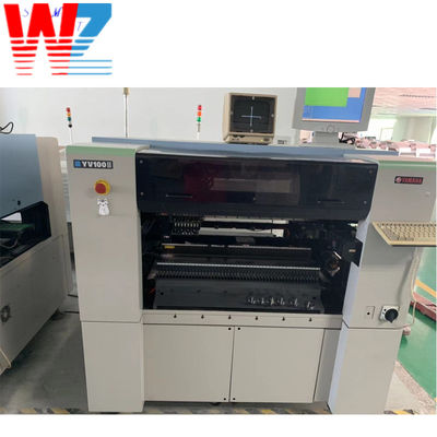
A distinct advantage of a YAMAHA Pick And Place Machine lies in its uncompromising structural integrity. For instance, models like the YS24 utilize heavy, single-cast metal frames equipped with dual-beam structures. This drastically dampens the microscopic vibrations generated during rapid acceleration. Capable of hitting speeds up to 72,000 components per hour, their premium models employ proprietary flying vision systems. These cameras capture and process complex grid images without requiring the placement head to pause. This allows manufacturers to sustain high throughput rates without sacrificing the strict ±0.03mm accuracy threshold.
Another dominant force in the high-accuracy automated assembly market is the Hanwha Techwin banner. These systems are widely recognized by production engineers for their exceptional component recognition capabilities and dynamic force control. The optical capabilities embedded within a precision samsung pick and place machine like the SM421 are engineered to tackle the unique reflective properties of solder balls.
Shiny metallic bumps easily cause glare, which can confuse standard camera algorithms and lead to faulty offset calculations. Advanced systems address this hurdle by integrating multi-stage lighting arrays, combining coaxial and side-angle illumination. This sophisticated lighting perfectly illuminates the spherical joints without generating harsh reflections. It guarantees that the vision algorithm pinpoints the exact center of each ball for flawless mapping, even for large components up to 55 millimeters square.
For production managers and process engineers tasked with upgrading their factory floors, evaluating new equipment requires a highly systematic approach. Below is a definitive checklist of crucial features that dictate a system capability to handle complex, high-density architectures.
The system must feature upward-looking cameras capable of resolving ultra-fine pitches. It is imperative to verify the camera field of view and megapixel count. The optical array must be capable of processing large integrated circuits in a single field of view, or possess the software intelligence to stitch multiple images together seamlessly without losing dimensional accuracy.
Vertical accuracy is just as critical as horizontal precision to prevent solder paste displacement. Look for specifications that offer programmable placement force, typically measured in Newtons. The equipment should empower engineers to set specific touchdown pressures based on the component mass and the specific rheology of the solder paste being utilized. Intelligent sensors monitor touchdown pressure in real-time, dynamically adjusting the deceleration of the nozzle to ensure a soft touchdown on every cycle.
Mechanical stability forms the bedrock of accuracy. Systems constructed with lightweight aluminum frames will inevitably suffer from resonance and micro-vibrations during high-speed gantry movements. A heavy-duty cast iron or reinforced steel frame, coupled with active vibration dampening technology, is absolutely necessary. This maintains micron-level precision over years of continuous, grueling operation.
Component placement accuracy actually begins at the pickup stage. If the feeder mechanism is loose or inaccurate, the vacuum nozzle will extract the chip off-center. While advanced vision systems can correct minor pickup errors, severe misalignments at the feeder level often result in the component being dropped or mounted incorrectly. Motorized, intelligent electric feeders are highly recommended over traditional pneumatic alternatives for maintaining consistent, reliable pickup coordinates.
Procuring a highly accurate mounting system is merely the first step. Preserving that accuracy over millions of production cycles requires rigorous operational discipline. Accuracy degradation is a creeping process, often going completely unnoticed until defect rates and rework costs begin to climb.
Preventative maintenance is the primary defense against accuracy loss. Vacuum nozzles must be cleaned daily using ultrasonic baths to prevent dust or solder paste buildup, which can cause components to sit unevenly on the head. Furthermore, the optical cameras and mechanical axes require strict periodic greasing and calibration. Using certified glass grids ensures the software pixel-to-millimeter ratio remains perfectly tethered to physical reality.
The physical environment of the factory floor plays a surprisingly massive role in long-term accuracy. Ambient temperature fluctuations cause the metal components of the gantry to expand or contract by several microns. Maintaining a strictly climate-controlled facility minimizes these variables. Additionally, the assembly line should be physically isolated from external vibrations caused by heavy machinery or passing forklifts. Floor vibrations easily transfer to the placement head during the critical touchdown phase.
When dealing with modern high-density packages, there is absolutely zero room for error. Because the critical connections are entirely hidden from view, achieving mathematically perfect alignment on the first attempt is paramount to maintaining profitability and minimizing rework.
Consequently, investing in highly accurate mounting equipment capable of sustaining strict tolerances is the most critical decision a production manager can make. Buyers must ruthlessly prioritize advanced upward-looking vision systems, dynamic vertical force control, and rigid mechanical frames. Reputable industry stalwarts continue to lead the market by providing the stability and software intelligence required for flawless, high-yield assembly.
If you are struggling with high defect rates or planning to upgrade your surface-mount lines for micro-scale production, selecting the right platform is critical. Explore our comprehensive inventory and find the perfect equipment tailored to your specific assembly requirements by visiting https://www.smtwenzhan.com to browse our industry-leading solutions.
Inaccurate placement leads to severe manufacturing defects such as solder bridging, cold solder joints, or open circuits. Because the joints are hidden underneath the component body, identifying and fixing these errors requires expensive inspection and complex thermal rework stations, which drastically increases production costs and bottlenecks the assembly line.
Generally, no. Entry-level or budget machines often lack the specialized upward-looking vision systems and the micron-level mechanical rigidity required to map and align hidden solder balls correctly. While they might occasionally succeed with very coarse-pitch components, they will consistently fail and cause high defect rates on modern, high-density electronics.
Vertical accuracy dictates the placement pressure applied to the component. If the machine presses too hard, the solder paste is squeezed outward, causing adjacent pads to short circuit during reflow. If it does not press hard enough, the component will not make proper contact with the paste, leading to open circuits or chips shifting as the board moves down the conveyor.
Calibration frequency depends heavily on your production volume and operating environment. Most equipment manufacturers recommend a basic calibration and vision check weekly or monthly. Additionally, a comprehensive professional calibration utilizing specialized glass plates should be performed annually to ensure the optical cameras and mechanical axes remain perfectly aligned for high-precision tasks.
Because the solder joints are hidden beneath the component body, standard overhead cameras cannot verify proper alignment. Facilities must utilize specialized automated optical inspection systems equipped with angled side-view cameras, or rely on inline automated X-ray inspection to look through the component and verify that the solder spheres are perfectly aligned with the printed pads prior to entering the reflow oven.
A standard, general-purpose machine without advanced upward-looking vision typically maxes out at a 0.8mm pitch. Attempting to place anything finer, such as 0.5mm or 0.4mm micro-packages, requires specialized high-resolution optics and closed-loop servo systems to guarantee the ±0.03mm accuracy necessary to prevent solder bridging.