Views: 0 Author: Site Editor Publish Time: 2026-10-09 Origin: Site
The electronics manufacturing sector demands massive throughput without compromising joint reliability. Mass-producing printed circuit boards relies heavily on automated bulk metallurgy. How exactly does a bare board, populated with loose components, transform into a fully functional electronic device in mere seconds?
This technical guide explores the mechanics of automated soldering technology. We will examine the core hardware anatomy, operational fluid dynamics, and compare high-throughput inline models with targeted selective systems. Production managers and manufacturing engineers can use these engineering insights to optimize assembly lines, reduce defect rates, and manage capital expenditures effectively.
Manual hand-soldering fails in high-volume production due to slow speeds and human fatigue. Automating this metallurgical bond slashes labor costs and stabilizes quality. A PCB Wave Soldering Machine achieves consistent, repeatable joints across thousands of units in a single shift.
A standard industrial system is a large, enclosed linear apparatus. It consists of several interconnected modules, each engineered to execute a specific phase of the welding process as the substrate travels down the line.
| Component | Primary Function | Engineering Detail |
|---|---|---|
| Conveyor System | Transports boards through the thermal zones | Utilizes titanium fingers or pallets to hold the substrate at a precise incline, typically 3 to 7 degrees, at a tightly controlled speed. |
| Flux Sprayer | Applies chemical cleaning agents | Uses ultrasonic or pneumatic spray nozzles to deposit an even, micro-thin coating of flux across the bottom layer. |
| Preheating Tunnels | Prepares the board for extreme heat | Emits infrared or forced convection heat to evaporate volatile solvents and prevent sudden thermal shock to ceramic components. |
| Solder Pot & Pump | Creates the standing molten crest | A titanium or cast-iron reservoir holding liquid alloy, equipped with a mechanical impeller pump to push the metal upward through a nozzle. |
| Cooling Fans | Solidifies the intermetallic joints | Utilizes high-velocity ambient air or nitrogen chilling to drop the board temperature safely and refine the alloy grain structure. |
The operation relies on a balance of chemistry, thermodynamics, and fluid mechanics. Rather than a simple dip, the process is strictly divided into four sequential steps.
Before any bonding occurs, metallic surfaces on the pads and component leads must be completely free of oxidation. The apparatus applies a chemical flux to the bottom of the board. This agent strips away existing oxide layers and prevents new oxidation from forming under extreme heat. Furthermore, it dramatically lowers the surface tension of the liquid metal to improve wetting. Modern platforms utilize programmable drop-jet or spray fluxers to minimize chemical waste.
Once fluxed, the conveyor transports the board into the preheating tunnels. Thermal profiling is absolutely critical at this stage. If the substrate heats up too rapidly, ceramic capacitors will crack due to thermal shock. The board itself may also warp. Preheating slowly raises the top-side temperature, usually settling between 80°C and 120°C. This gradual bake evaporates the volatile solvents in the flux and fully activates its cleaning properties.
Building on this thermal foundation, the board passes over the heated pot. An internal impeller pump forces the molten alloy through a specially designed nozzle. This creates a standing, continuous crest of liquid metal. As the bottom of the PCB grazes this wave, capillary action takes over. The liquid is drawn up into the plated through-holes and wraps tightly around the component leads. The slight incline of the conveyor helps excess liquid peel away cleanly as the board exits the crest, preventing unwanted shorts.
Immediately after exiting the wave, the board enters the cooling zone. A controlled cooling rate of 2°C to 5°C per second is vital. Rapid cooling refines the grain structure of the intermetallic compound. This creates a strong, shiny, and structurally sound connection. In contrast, if the cooling is too aggressive, it induces mechanical stress and micro-cracking within the joints.
As board real estate becomes increasingly dense, manufacturing engineers must carefully choose between standard inline platforms and targeted selective systems.
A traditional SMT wave solder machine is engineered for high-volume, low-mix production environments. In this setup, the entire bottom of the board is exposed to the liquid metal. When integrating this into a surface mount line, manufacturers use specialized adhesives to glue components to the bottom of the board. The substrate then runs through the crest, soldering the through-hole pins and the glued components simultaneously. It is incredibly fast but lacks localized thermal control.
When dealing with intricate, double-sided boards containing highly sensitive surface-mount components, a full thermal wash will cause catastrophic damage. Selective soldering becomes indispensable here. This method utilizes a miniature, programmable fountain attached to a robotic XYZ gantry. Instead of washing the entire surface, the machine moves the mini-fountain to target individual through-hole joints point-by-point. This completely avoids adjacent components. These offline units operate independently from the main inline conveyor, offering maximum agility for high-mix, low-volume batches.
The push for extreme miniaturization in IoT devices, aerospace, and automotive electronics is forcing a rapid evolution in hardware design. Current industry data highlights a massive shift toward nitrogen-inerted environments. The global transition to lead-free alloys, such as SAC305, introduced severe thermal challenges. Lead-free alloys possess higher melting points and exhibit sluggish wetting behavior. Flooding the tunnel with nitrogen displaces ambient oxygen. This cuts dross formation by up to 80% and significantly improves the capillary flow of the alloy.
Specifically, smart factory integration is transitioning from a luxury to a baseline requirement. Modern automated platforms now feature closed-loop feedback sensors, real-time data logging, and predictive maintenance alerts. These systems can automatically adjust preheat gradients and conveyor speeds on the fly, reducing the reliance on operator intuition and ensuring strict quality control across shifts.
Evaluating this equipment requires an objective look at its engineering value versus its operational constraints.
The primary commercial benefit is massive throughput. A well-calibrated platform processes thousands of boards per shift. Machine-controlled parameters ensure strict consistency, guaranteeing that the first board and the ten-thousandth board share the exact same metallurgical quality.
However, these systems require a substantial initial capital investment and consume significant factory floor space. They also necessitate robust exhaust infrastructure to vent hazardous chemical fumes. Additionally, molten metal reacts with ambient oxygen to form dross. This oxidized waste requires scheduled maintenance downtime for skimming and incurs costs for safe ecological disposal.
Running this equipment effectively requires strict adherence to standard operating procedures. Operators must manage a complex thermal and chemical environment.
Selecting the correct apparatus requires matching specific technical parameters directly to your facility layout and output goals. Do not base purchasing decisions solely on the initial sticker price.
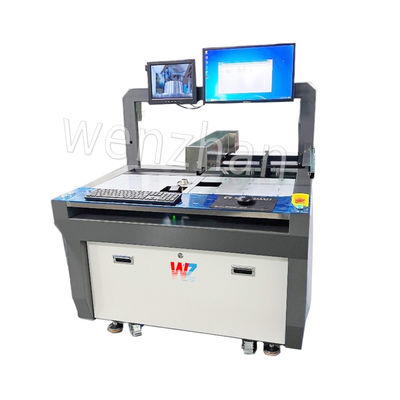
For high-throughput, low-mix environments, robust inline models are the standard. Equipment like the WZ-550 series features elongated, multi-zone preheating and dual-wave capabilities. This is critical for thick, multi-layer PCBs that require deep thermal penetration to achieve proper hole-fill.
In contrast, if your facility processes high-mix, low-volume batches with dense double-sided layouts, an Offline Selective Wave Soldering Machine is the strategic choice. Look for specifications that include precision XYZ robotic gantries, drop-jet fluxers to limit chemical spread, and micro-nozzles ranging from 3mm to 8mm for pinpoint accuracy.
For mid-range operations needing a balance of speed and footprint, compact models like the WZ-250 provide essential wave dynamics without consuming massive floor space. Always evaluate the total cost of ownership. Factor in daily power consumption, nitrogen usage rates, alloy capacity, and the regional availability of technical support.
Investing in automated soldering equipment is a critical step in scaling electronics manufacturing. Understanding the mechanics of fluxing, preheating, and fluid dynamics is essential for engineering reliable products. By matching your production volume, board complexity, and layout density to the right machine specifications, your facility will achieve lower defect rates and a rapid return on investment. Ready to upgrade your assembly line? Evaluate your specific production needs and source reliable, high-performance equipment directly from https://www.smtwenzhan.com to find the perfect system for your factory floor.
A wave system passes the bottom of the PCB over a standing crest of liquid metal, making it ideal for securing through-hole components. A reflow oven is used for surface mount technology. It melts pre-applied solder paste to attach components directly to the surface of the board using precisely controlled heated air or infrared radiation.
Yes. In mixed-technology manufacturing, surface mount components are glued to the bottom of the board and cured in an oven. The board then passes through the liquid crest, which secures both the glued components and the through-hole pins simultaneously.
Bridging occurs when liquid metal fails to peel away cleanly, connecting two adjacent pins. This is typically caused by inadequate flux volume, a conveyor speed that is too fast, or a wave height that is set too high. Adjusting the conveyor incline and verifying flux deposition usually resolves the issue.
Dross is the oxidized waste that forms on the surface of the heated pot when liquid metal reacts with oxygen in the ambient air. If not regularly skimmed off by the operator, it alters the fluid dynamics of the crest and can get pulled into the joints, causing structural defects.
Operators should skim surface dross at least once per shift. A full chemical analysis of the alloy should be conducted every three to six months to check for copper or iron contamination. If contamination exceeds acceptable thresholds, the pot must be partially or fully drained and replenished with fresh alloy.