Views: 0 Author: Site Editor Publish Time: 2026-10-11 Origin: Site
Did you know a tiny temperature shift can ruin entire printed circuit board batches in a matter of seconds? Poor thermal control is the leading culprit behind frustrating manufacturing defects. These issues range from stubborn solder bridging to completely fractured components. To eliminate these costly errors, engineers need a precise thermal map of the entire soldering process.
Precision thermal management is now the defining factor between a profitable production run and a scrapped batch. Operators can no longer rely on estimated machine settings or historical guesswork. In this comprehensive guide, you will learn how to properly set up thermocouples, execute a test run, and read thermal curves accurately. Mastering these steps will instantly optimize your assembly line.
The electronics manufacturing sector is leaning heavily toward high-density interconnect designs and strict RoHS-compliant lead-free alloys. Consequently, the thermal process window has shrunk drastically. Recent industry analyses highlight a major shift toward automated quality control. Automotive electronics and advanced telecommunications demand zero-defect manufacturing. This strict requirement pushes factories to adopt continuous, real-time thermal monitoring rather than periodic checks.
Furthermore, flux formulations are becoming increasingly specialized. Water-soluble and no-clean fluxes require highly specific activation temperatures. Without a highly accurate thermal profile, activating these modern chemicals is nearly impossible. Modern production lines are integrating smart profiling software that uses historical data to predict thermal anomalies before they cause board failure.
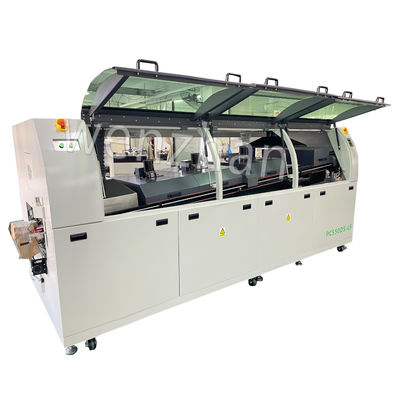
A thermal profile is the exact time-versus-temperature curve that a board experiences as it travels through the soldering equipment. It acts as a diagnostic thermal map. This map documents the specific temperatures reached at various points on the board over a defined period. This profile is fundamentally the heartbeat of any SMT wave solder machine. It dictates the metallurgical reliability and mechanical strength of the final solder joints.
Without a documented thermal curve, operators are essentially running the production line blind. This lack of visibility significantly increases the risk of catastrophic board failure.
The primary objective of capturing this data is to ensure that the thermal environment meets the strict chemical and physical requirements of the soldering process.
While standard machine readouts provide baseline metrics, gathering accurate thermal data requires specialized equipment. This gear must withstand the harsh environment inside a soldering tunnel. Relying on machine sensors alone is insufficient. The temperature of the heating elements differs significantly from the actual temperature on the board surface.
Industry-standard profiling devices are essential for this task. These insulated data loggers are designed to ride along the conveyor directly behind the test board. They record real-time temperature data at multiple intervals per second. The thermal barrier protecting the logger must be robust enough to survive direct exposure to the preheaters and the intense radiant heat of the molten alloy.
Thermocouples are the actual sensors that physically measure the heat. For these high-temperature applications, Type K thermocouples are universally recommended. It is critical to use low-mass thermocouples, typically 30 or 36 AWG. This ensures the sensor itself does not act as a heat sink, which would artificially lower the recorded temperature.
Securing the thermocouples to the test board is a make-or-break step. High-temperature epoxy provides an excellent, permanent bond and good thermal conductivity. However, it requires a long curing time. Aluminum tape is the most common method for temporary setups. Aluminum conducts heat efficiently, ensuring the thermocouple tip accurately reflects the board temperature.
Profiling should never be done on a random piece of scrap material. Operators must use a dedicated Golden profile board. This specific panel must perfectly mimic the actual production board in terms of physical dimensions, layer count, copper weight, and component density. Thermal mass dictates how quickly a board absorbs and dissipates heat. Using a bare board to profile for a heavily populated assembly will result in drastically inaccurate baseline settings.
The integrity of your thermal data relies entirely on the precision of your thermocouple setup. Poor placement or loose attachments will yield false spikes. This inevitably leads to incorrect machine adjustments and subsequent quality defects.
To capture a comprehensive thermal footprint, sensors must be placed strategically across the board. Standard practice requires a minimum of three to five measurement points. The leading edge is the first part to hit the molten wave, experiencing rapid temperature changes. The trailing edge often retains heat the longest. The center of the board is prone to physical sagging and is often the coolest part during the preheat phase. Finally, high thermal mass areas with large copper planes require significantly more heat to reach the target temperature.
Attaching the thermocouple bead requires a delicate touch. You must place the welded tip directly against the target pad. Next, cover it tightly with a small square of aluminum tape. Press down firmly with a spudger to eradicate any microscopic air pockets. Trapped air acts as a thermal insulator, skewing your readings.
When measuring through-hole penetration, insert the thermocouple bead into the barrel of the hole from the top side. Secure the wire flat against the board surface. This ensures the bead remains suspended inside the hole without protruding out the bottom, where it could be sheared off by the solder pump.
With the test board prepared and the data logger initialized, the next phase is executing the physical run. This process establishes the baseline performance of the equipment under current environmental conditions.
Before introducing the test board, operators must input the initial settings into the SMT assembly wave soldering machine. For example, standard systems often feature adjustable conveyor speeds typically set between 0.8 to 1.5 meters per minute. This specific speed dictates the total time the board spends in the tunnel. It directly impacts the dwell time.
Set the bottom and top preheaters to achieve the target topside temperature. For modern lead-free flux formulations, this target is usually between 100 and 120 degrees Celsius. The solder pot temperature must be set to the specific alloy specification, such as 260 degrees Celsius for standard lead-free alloys.
Initiate the data logger recording mode just before placing the setup onto the conveyor rails. Load the test board in the exact same orientation as the actual production run. Look through the viewing glass as the board travels. Verify that the flux spray evenly coats the bottom side without bleeding through the vias. Observe the contact with the main solder wave. The liquid metal should gently kiss the bottom of the board with a smooth, laminar flow.
Generating the graph is only half the battle. The true diagnostic value lies in interpreting this time-versus-temperature curve. A standard profile is divided into four distinct zones.
| Thermal Zone | Traditional Tin-Lead Target | Lead-Free Target | Primary Purpose |
|---|---|---|---|
| Preheat Slope | 1 to 2 degrees Celsius per second | 1 to 2.5 degrees Celsius per second | Evaporate flux solvents safely without thermal shocking components. |
| Thermal Soak | 80 to 100 degrees Celsius | 100 to 120 degrees Celsius | Activate chemical cleaning agents to remove copper oxides. |
| Peak / Dwell Time | 210 to 220 degrees Celsius (3-4 sec) | 235 to 245 degrees Celsius (3-5 sec) | Achieve liquidus state for optimal through-hole capillary action. |
| Cooling Slope | -2 to -4 degrees Celsius per second | -3 to -5 degrees Celsius per second | Solidify the joint quickly to form a fine, strong grain structure. |
The preheat zone is the first section of the curve. The curve should show a steady, linear climb. A slope steeper than 2 degrees Celsius per second risks micro-cracking in ceramic capacitors. As the board approaches the wave, the curve should flatten out slightly into a soak phase. During this soak, the flux chemically activates.
The peak temperature represents the moment the board contacts the molten metal. On the graph, this appears as a sharp, distinct spike. The width of this spike represents the dwell time. Too short, and the hole fill will be incomplete. Too long, and the copper pads may dissolve into the solder pot.
When post-soldering inspection reveals defects, this thermal graph becomes your primary diagnostic tool. Manipulating specific zones of the curve allows operators to resolve mechanical and metallurgical issues systematically.
Solder bridging occurs when molten alloy fails to separate between adjacent pins. This creates an unintended electrical short. It is often caused by the solder cooling too slowly as it exits the wave, or by inactive flux. To resolve this, check the preheat soak zone on your graph. Increasing the preheat temperature slightly allows the solder to drain back into the pot more efficiently.
Insufficient hole fill happens when the solder fails to travel all the way up the through-hole barrel. This is a classic symptom of inadequate top-side preheating. If the top of the board is too cold, the molten solder freezes before it can complete its capillary action. The solution is to increase the top-side preheat temperatures and verify the dwell time.
Small spheres of solder stuck to the bottom of the board are known as solder balls. Violent splattering and solder balls are directly linked to an incorrect preheat slope. If the ramp rate is too fast, the volatile solvents in the flux do not fully evaporate. When these wet solvents hit the molten wave, they boil explosively. Flattening the preheat curve ensures complete solvent evaporation.
Modern board designs often cram sensitive surface-mount devices right next to heavy through-hole connectors. In these scenarios, traditional mass soldering is often too aggressive. Exposing the entire bottom surface of a mixed-technology board to a molten bath can reflow previously soldered joints. This requires a shift in both equipment selection and profiling methodology.
If you process high-volume, uniform boards with standard through-hole components, a traditional continuous-flow system is ideal. These robust machines utilize wide, cascading waves to solder the entire board simultaneously. They rely on global thermal uniformity across the entire substrate.
Conversely, complex mixed-technology boards demand an Offline Selective Wave Soldering Machine. These advanced systems utilize a miniature, programmable solder fountain mounted on a robotic gantry. Because the heat application is highly localized, the thermal profile represents a series of isolated thermal events rather than a uniform blanket of heat. You must attach thermocouples directly to the specific component pins targeted by the micro-nozzle. Furthermore, selective machines allow engineers to program unique dwell times for every individual nozzle touch, offering unparalleled control over the soldering process.
Creating a perfect thermal profile is a meticulous blend of precise thermocouple setup, accurate data collection, and expert curve analysis. It is the most effective way to guarantee the metallurgical integrity of your assemblies while protecting sensitive components from thermal damage.
Remember that profiling is never a one-time task. You must perform regular profile checks to account for gradual machine wear, environmental fluctuations on the factory floor, and variations in new flux batches. Maintaining strict control over your thermal process window will drastically reduce rework and elevate your overall production yield.
Ready to upgrade your manufacturing capabilities and eliminate soldering defects? Visit https://www.smtwenzhan.com to explore our comprehensive catalog of reliable surface mount technology machinery. Contact our technical engineering team today for a custom consultation on optimizing your factory floor.
Establishing a rigorous schedule for thermal profiling is foundational to maintaining a predictable, high-yield manufacturing environment. Ideally, a comprehensive profile must be captured during any new product introduction, as every unique assembly possesses a different thermal mass. Furthermore, you should run a profile immediately following any significant machine maintenance, such as replacing heating elements or adding fresh flux. Quality control standards recommend verifying the thermal parameters of your equipment at least once a week to combat natural process drift.
Dwell time is the exact duration that a specific point on the board remains in direct physical contact with the molten alloy. Empirical data indicates that the optimal dwell time generally falls between 3 to 5 seconds. This specific window allows sufficient time for capillary action to draw the liquid metal upward through the plated through-hole. This action displaces flux volatiles and forms a structurally sound fillet. Deviating from this window risks either insufficient hole fill or excessive copper dissolution.
Absolutely not. Attempting to process lead-free solder alloys using a thermal profile designed for traditional leaded solder is a guaranteed path to massive quality control rejections. Traditional leaded solder is a eutectic alloy with a melting point of 183 degrees Celsius. Modern lead-free alloys have significantly higher melting points. To achieve proper fluid dynamics with lead-free solder, the peak temperature must reach between 255 and 265 degrees Celsius. The fluxes formulated for lead-free processing also require completely different preheat slopes.
Different flux chemistries require specific thermal energy to function properly. VOC-free water-based fluxes require a longer, hotter preheat soak to evaporate the water content completely before hitting the wave. If water remains, it turns to steam instantly, causing violent solder splattering. Conversely, alcohol-based rosin fluxes evaporate much faster and can burn off entirely if the preheat zone is too hot or too long, leaving the pads unprotected from oxidation.
Jagged lines or sudden, impossible temperature drops on a thermal profile graph almost always indicate a mechanical sensor failure rather than an actual temperature fluctuation. This usually happens when the aluminum tape loses its adhesive grip, causing the thermocouple bead to lift off the board surface intermittently. It can also be caused by degraded thermocouple wires that have micro-fractures inside the insulation. Always inspect your sensor attachments and wire integrity before running a profile.