Views: 0 Author: Site Editor Publish Time: 2026-10-01 Origin: Site
Did you know a single thermal misstep can dictate the entire quality of a Printed Circuit Board? In the high-stakes world of Surface Mount Technology, precision is everything. Poor heat distribution routinely ruins otherwise perfect surface mount boards, turning expensive components into scrap.
A reliable industrial heating machine solves this exact problem. Simply put, it melts solder paste to form secure, permanent electrical connections between microscopic components and the bare board. In this comprehensive guide, we break down the mechanics of how this crucial equipment works. We explore the intricacies of its heating zones, the science behind thermal profiles, and its strategic placement within an automated assembly line. Whether you are a production engineer troubleshooting defects or a procurement manager evaluating your next capital investment, this post outlines exactly what to look for in high-quality manufacturing machinery.
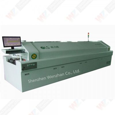
At its core, this equipment acts as a highly advanced thermal processing tunnel. Before a board ever enters this tunnel, a stencil printer applies solder paste, which is a precise, sticky mixture of metal alloy powder and chemical flux. As the populated board travels along the internal conveyor belt, the ambient temperature carefully rises in a strictly controlled sequence.
This calculated heat causes the paste to undergo a physical transformation. First, the flux activates. It bubbles slightly as it cleans oxidation off the metal pads. Then, the alloy transitions into a liquid, flowing smoothly over the component terminals. As the board exits the heating chambers and hits the cooling section, you can physically see the metal shift from a dull liquid to a shiny, solid state. These newly formed permanent joints give the circuit its electrical heartbeat.
Historically, older setups relied on infrared heating. This often led to nightmares on the factory floor. Dark-colored components absorbed heat much faster than light ones, causing uneven melting. Today, the industry standard relies entirely on forced-air convection. Powerful blowers push hot air uniformly across the board. This guarantees that all components reach the target temperature simultaneously, regardless of their color, shape, or placement density.
The electronics manufacturing sector has largely abandoned older through-hole techniques in favor of surface mount methods. This technological shift allows parts to be placed directly onto the surface of the board, making modern smartphones thinner, faster, and infinitely more complex.
Convection heating serves as the backbone of this transition. Traditional wave soldering is far too aggressive for microscopic surface-mount parts and easily bridges closely spaced pads with excess metal. In contrast, convection provides the delicate, highly regulated environment necessary to process high-density boards. It effortlessly handles miniature components like ball grid arrays without inducing thermal damage.
To achieve a flawless joint without compromising sensitive electronic packages, the heating process cannot be rushed. It must be gradual and strictly regimented. Engineers accomplish this by dividing the internal chamber into four distinct thermal zones.
The primary objective here is to safely elevate the temperature of the substrate and its attached components from room temperature to a target baseline. This step requires patience. If an operator programs the board to heat too quickly, the sudden expansion of disparate materials causes thermal shock. You might actually hear the microscopic cracking of ceramic capacitors. Furthermore, rapid heating boils the volatile solvents in the paste too aggressively. This causes them to splatter and leave tiny, short-circuit-causing solder balls scattered across the board. From a practical standpoint, the industry-recommended ramp-up rate is strictly kept between 1.0 and 3.0 degrees Celsius per second.
Once the assembly reaches approximately 150 degrees Celsius, it transitions into the thermal soak zone. The goal shifts from merely heating to achieving thermal equilibrium. Because a circuit board features varying copper densities, thick grounding planes, and drastically different component sizes, parts naturally heat at varying speeds. The soak zone gives the slower heating areas time to catch up.
Simultaneously, the flux reaches its full activation state. It acts as a chemical scrubbing agent, stripping away invisible surface oxidation from the bare pads and component leads. Without this vital cleaning action, the liquid metal will simply bead up rather than wetting to the pad, resulting in structurally weak connections.
This is where the actual magic happens. The temperature pushes past the specific melting point of the alloy, a threshold known as the Liquidus temperature. For standard lead-free materials, this sits around 217 degrees Celsius. Peak oven temperatures typically spike between 235 and 250 degrees Celsius.
Operators monitor two vital metrics during this phase, specifically Peak Temperature and Time Above Liquidus. If the peak is too hot or the duration drags on too long, the board substrate can scorch. Sensitive silicon dies can also suffer internal failure. Conversely, if the heat is insufficient, the metal never fully liquefies. This leaves behind brittle, highly resistive cold joints that will inevitably fail in the field.
Immediately after the intermetallic bonds form, the board whisks into the cooling zone. The objective is to rapidly drop the temperature to solidify the liquid metal.
A controlled descent, typically between 2.0 and 4.0 degrees Celsius per second, is critical. Freezing the metal quickly promotes a fine-grain crystalline structure. This yields a mechanically robust joint capable of withstanding physical stress and vibration. However, blasting it with too much cold air too fast can warp the substrate or induce thermal stress fractures in the newly soldered components.
A thermal profile is the specific temperature-over-time curve programmed into the machine software. Think of it as the master recipe for the soldering process. Every board possesses a unique thermal mass. A thick copper power board behaves entirely differently than a paper-thin flexible LED strip. Consequently, there is no universal setting. Lead-free pastes possess notoriously tight process windows, making strictly calibrated profiles an absolute necessity to prevent exceeding component thermal limits.
Dialing in the perfect recipe is a hands-on process. Engineers start by attaching tiny temperature sensors directly to a sacrificial test board using high-temperature tape. They place these sensors on critical areas, such as under a massive processor, on a tiny resistor, and near the board edge. This test board runs through the chamber alongside a data-logging profiler. By analyzing the resulting graph, operators tweak individual zone temperatures and conveyor belt speeds until the curve perfectly matches the paste manufacturer specifications.
When defects appear at the end of the line, the thermal profile is usually the primary suspect. Adjusting the curve can resolve several common issues on the factory floor.
The electronics manufacturing sector is currently undergoing a massive shift driven by miniaturization and high-density packaging. As consumer devices demand more computing power in smaller footprints, assemblers increasingly rely on microscopic passive components. This relentless shrinking leaves zero margin for thermal errors, pushing equipment manufacturers to innovate rapidly.
Specifically, we are seeing a growing industry reliance on smart automation. Forward-thinking manufacturers are adopting artificial intelligence to assist with profiling software. These smart systems simulate and predict thermal behavior based on board layout data before a single test board is ever sacrificed. This drastically cuts down changeover times and minimizes material waste.
Furthermore, the demand for high-reliability electronics in automotive and aerospace applications has pushed nitrogen-capable chambers from a luxury to an industry standard. Displacing oxygen with nitrogen gas prevents oxidation during peak heating phases. This results in superior wetting forces and significantly lower voiding rates, ensuring the long-term reliability of mission-critical circuits.
In a modern manufacturing facility, thermal processing does not happen in isolation. It operates as a highly synchronized piece of a larger automated puzzle. A typical high-yield assembly line follows a strict operational sequence to ensure maximum efficiency.
The physical transition between the mounter and the heating chamber is an incredibly delicate juncture. At this exact moment, the components are held to the board solely by the weak tackiness of the un-melted paste.
Conveyor systems must utilize standard communication protocols to seamlessly transfer the populated board without sudden jerks or vibrations. Even a minor mechanical shock during this handoff can shift micro-components off their designated pads. Once the board enters the heating tunnel, the continuous mesh belt takes over, maintaining a calibrated speed that dictates the thermal profile.
Placing the inspection machine directly after the cooling zone creates a rapid feedback loop for quality control. If the scanner detects a sudden spike in defects, such as widespread bridging on integrated circuits, engineers can immediately halt the line. They can trace the root cause back to the thermal profile in real time. This immediate data prevents a localized parameter error from ruining an entire production batch.
When evaluating thermal processing machinery, the mechanical specifications directly dictate your final yield rate. High-volume, defect-free production requires specialized features designed for absolute stability.
| Specification | Standard Prototype Oven | Industrial Production Oven |
|---|---|---|
| Heating Zones | 4 to 6 Zones | 8 to 12 Zones |
| Startup Power | 1500W - 2500W | 4800W and above |
| Conveyor System | Basic Mesh Belt | Edge-pin Chain + Center Mesh Support |
| Thermal Control | Basic Thermostat | Closed-loop PID Controllers |
The precision of your thermal curve depends entirely on the number of heating zones available. While small benchtop prototype units feature limited zones, industrial production demands granular control. Upgrading to an eight-zone architecture provides the foundation for a Consistent Soldering SMT Reflow Oven. Featuring a robust 4800W startup power, these machines allow for a smoother, highly gradual transition between stages. This ensures heavy power boards heat evenly without thermally shocking delicate sensors.
During the peak phase, the metal is entirely liquid. If the internal conveyor chain stutters or vibrates, components can literally float out of alignment. Premium machines utilize heavy-duty, vibration-free transport systems. They often combine edge-pin chain conveyors to handle double-sided rigid boards with center mesh belts to prevent thin flexible circuits from sagging in the middle of the heated tunnel.
In addition, modern equipment relies heavily on data-driven automation. The control software acts as the brain, utilizing closed-loop PID controllers to monitor and adjust zone temperatures in milliseconds. Built-in alarm systems continuously monitor for temperature drops, automatically alerting operators if a blower motor fails before defective boards are produced.
When procuring heavy industrial machinery, safety and compliance must remain top priorities. The Conformité Européenne mark is a critical baseline requirement. It indicates that the equipment complies with stringent European Union directives regarding health, safety, and environmental protection.
Specifically, this certification guarantees that high-voltage heating elements are correctly insulated, emergency stop protocols are fail-safe, and electrical emissions will not disrupt other sensitive equipment on your factory floor. For standard industrial setups, a reliable 220V power configuration is highly sought after. Facilities looking for robust performance often invest in a CE smt reflow soldering oven to ensure seamless integration into existing power grids while maintaining strict safety standards.
Global environmental mandates have forced the industry to abandon traditional tin-lead materials. Today, lead-free alloys are the definitive standard.
This chemical shift drastically changed thermal requirements. Traditional materials melted at 183 degrees Celsius, whereas modern alloys require approximately 217 degrees Celsius. Consequently, peak temperatures are much higher. To handle this sustained thermal load without premature burnout, your facility must utilize a dedicated CE lead free reflow oven. These specific units are engineered with superior thermal insulation, upgraded blower motors, and high-wattage heaters capable of running around the clock.
Selecting the optimal machine requires matching technical specifications to your unique production environment. Keep these practical metrics in mind during your evaluation process.
The heating chamber undeniably serves as the beating heart of the assembly process. While printers and robotic mounters prepare the materials, the thermal tunnel physically forges the electrical connections. Mastering the mechanics of heating zones and strictly calibrating temperature profiles remains the ultimate key to minimizing defects, reducing costly rework, and maximizing overall yield.
Whether you are assembling standard consumer electronics, complex medical devices, or high-power lighting boards, the quality of your thermal equipment dictates the reliability of your final product. Investing in certified, multi-zone machinery guarantees that your facility meets strict safety compliance while consistently delivering top-tier manufacturing quality.
Take the time to evaluate your current line capacity and consult with reputable manufacturers. If you are ready to upgrade your production capabilities, explore the high-performance 8-zone and 10-zone models available at smtwenzhan.com to find the perfect fit for your specific manufacturing needs.
These machines serve different primary purposes in circuit board assembly. Wave equipment is predominantly used for older through-hole components. It passes the bottom of a board over a cascading wave of molten liquid metal, which wicks up into the holes. Conversely, a thermal convection chamber is built for surface mount devices. It uses heated forced air to melt precise deposits of paste that were applied to the board surface prior to component placement.
The ideal number depends entirely on your production complexity. For basic prototyping or low-volume runs of simple boards, a four to six-zone machine may suffice. However, for high-volume, complex production, an eight-zone to twelve-zone machine is highly recommended. The additional zones provide finer control over the thermal gradient, preventing thermal shock and ensuring absolute consistency across heavy multi-layer boards.
Environmental regulations have established lead-free materials as the global standard. These modern alloys require significantly higher melting temperatures compared to older materials. A specialized lead-free machine is built with enhanced thermal insulation, stronger heating elements, and robust cooling systems to handle these extreme temperatures safely and consistently without degrading the equipment lifespan.
You should run a new thermal profile using a test board and sensors every time you introduce a new circuit design, change to a different type of paste, or perform major maintenance on the equipment. Because different boards have different thermal masses, the recipe must be adjusted accordingly. High-yield manufacturing facilities also run weekly verification profiles as part of their standard quality assurance protocols.
Solder balling typically occurs when the preheat ramp-up rate is too aggressive. Rapid heating causes the volatile solvents within the paste to boil and outgas violently, splattering tiny droplets of liquid metal across the solder mask. Adjusting the initial heating slope to a gentler 1.0 to 2.0 degrees Celsius per second usually resolves this defect entirely.
Yes, processing double-sided boards requires two separate passes. During the second pass, the components on the bottom side are held securely in place by the surface tension of the previously melted liquid metal. Engineers often use a slightly lower peak temperature for the second pass to minimize thermal stress on the already-soldered components.