Views: 0 Author: Site Editor Publish Time: 2026-10-21 Origin: Site
Precision is the absolute cornerstone of modern electronics manufacturing. Have you ever seen a single miscalibrated setting ruin thousands of circuit boards? It happens more often than you think. The entire soldering process demands a perfect thermodynamic and chemical balance. Manufacturers face catastrophic defect rates, costly rework, and field failures without this equilibrium.
This process is far from a simple mechanical step. It is a highly orchestrated sequence of thermal events and fluid dynamics. Mastering these interconnected variables separates flawless joints from massive financial losses. Here, we outline the exact parameters required to optimize your assembly line, regardless of whether you are running a traditional high-volume setup or utilizing precision localized technologies.
Before diving into specific machine settings, we must acknowledge current manufacturing trends. The industry is experiencing a massive shift toward high-density interconnect designs. This shift is driven largely by 5G telecommunications, advanced aerospace electronics, and the booming electric vehicle market. These sectors demand absolute zero-defect reliability.
Consequently, process windows are shrinking rapidly. Traditional bulk processes are increasingly being supplemented by highly localized, data-driven precision techniques. Engineers now require equipment that offers tighter thermal control and dynamic fluxing capabilities to handle complex, mixed-technology boards.
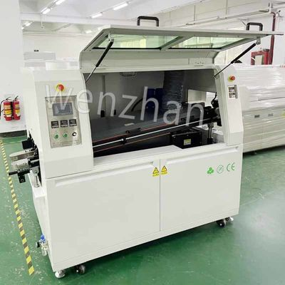
To achieve zero-defect manufacturing, operators must first understand that bulk soldering is a continuous, interdependent ecosystem. It relies on passing a board over a pan of molten alloy, where a mechanical pump creates a standing wave. This wave washes over the bottom of the board, adhering to exposed metallic pads and wicking into through-hole component leads simultaneously.
The system is built upon four foundational pillars:
It is critical to recognize the cascading effect of these stages. Poor chemical preparation will render the preheat stage ineffective. Consequently, improper preheating will inevitably lead to catastrophic structural defects during the final bonding phase.
Flux serves as the chemical foundation of a reliable electrical connection. Its primary purpose is to reduce surface tension and dissolve the stubborn oxide layers that naturally form on metal surfaces. Controlling how this chemical is deposited is the very first step in line optimization. Picture a densely populated FR4 board sliding over the fluxer. If the coating is uneven, the entire downstream process is compromised.
Modern assembly equipment predominantly utilizes atomized spray systems. Controlling the volume applied and the air pressure used to atomize it is vital. When calibrating a PCB Wave Soldering Machine, operators must prioritize a uniform mist. Applying an excessive volume leads to messy, sticky residues. These residues can cause long-term reliability issues like electromigration. In contrast, inadequate volume results in poor wetting. This leaves oxides on the board that cause bridges, skips, and cold joints. The spray pressure must be tuned so the mist coats the board evenly without bouncing off the substrate.
For liquid chemical preparations, monitoring specific gravity is a non-negotiable parameter. As the fluid sits in the reservoir, the alcohol solvent gradually evaporates. This causes the concentration of solid materials to spike. If the density becomes too high, the fluid thickens, leading to excessive residue and potential nozzle clogging. Automated density controllers or regular manual hydrometer checks are required to add thinner and maintain the exact chemical ratio.
When processing through-hole components, the liquid must travel up inside the plated through-hole to ensure the molten alloy will follow. The upward pressure of the spray system must be tuned to achieve optimal penetration depth. The goal is to ensure the chemistry reaches the top of the barrel to facilitate capillary action. However, operators must avoid flooding the top side of the printed circuit board, which could contaminate surface-mount devices or test points.
Once chemically prepped, the board enters the preheating zone. The objective here is threefold. First, evaporate the solvents to prevent explosive outgassing upon hitting the wave. Second, activate the chemical cleaning agents. Third, gently elevate the temperature of the board to prevent thermal shock upon contact with the liquid metal.
The rate at which the substrate heats up is known as the ramp rate or slope. Empirical data shows that the ideal heating rate is typically between 1 and 2 degrees Celsius per second. If the slope is too aggressive, the rapid thermal expansion can cause severe damage. Imagine multi-layer ceramic capacitors cracking under the stress, or the FR4 substrate delaminating internally. A controlled, steady climb is mandatory.
Thermal profiling requires monitoring both the component side and solder side of the assembly. The bottom side typically needs to reach between 110 and 130 degrees Celsius to ensure proper activation. This depends on the specific chemistry used. However, operators must strictly monitor the top-side temperature. Heat-sensitive components must never exceed their maximum thermal thresholds, which is usually capped around 100 to 120 degrees Celsius during this phase.
Soak time refers to the duration the board remains at the target activation temperature before making contact with the liquid alloy. This parameter dictates how thoroughly the oxidation is cleaned. If the soak is too short, the chemical agents will not fully react. Conversely, if it is too long, the protective layer will burn off entirely. This leaves the board exposed to rapid oxidation just as it enters the bonding phase.
The wave module is the undeniable heart of the operation. This is the exact moment where mechanical strength and electrical conductivity are permanently forged. The fluid dynamics and thermal characteristics of the molten alloy must be precisely governed.
The operating temperature of the pot is dictated entirely by the alloy being utilized. For traditional leaded solder, the eutectic melting point is 183 degrees Celsius. The pot is typically maintained between 240 and 250 degrees Celsius. For modern RoHS-compliant lead-free alloys like SAC305, the melting point is higher. This necessitates a pot temperature between 255 and 265 degrees Celsius. Operating below these parameters increases viscosity, leading to webbing. Operating above them accelerates copper dissolution, literally eating away the pads on the board.
Wave height determines how deeply the assembly is submerged into the molten metal. Industry standards dictate that the board should be immersed by one-half to two-thirds of its total thickness. If the crest is too low, it will lack the upward pressure needed to fill the through-holes via capillary action. If the crest is too high, it risks flooding the top side of the board, destroying components and causing massive short circuits.
Dwell time is the exact number of seconds a specific point on the substrate remains in contact with the liquid wave. The standard window is incredibly narrow, usually spanning just 2 to 4 seconds. Too short, and the base metals fail to reach the necessary temperature to form a proper intermetallic compound. This results in weak, cold joints. Too long, and prolonged exposure causes excessive intermetallic compound growth. This makes the joint brittle and burns the substrate.
When operating an advanced SMT wave solder machine designed for mixed-technology boards, like the WZ-550 series, operators utilize dual waves. The first is a turbulent chip wave driven by high pump speeds. It is engineered to force liquid metal into tight spaces and prevent shadowing behind small surface-mount components. The second is a smooth, laminar lambda wave. This cleans up excess material and forms the final, perfect fillet on through-hole pins.
The physical movement of the board through the tunnel is just as critical as the thermodynamics. The conveyor system acts as the mechanical backbone that ties all other parameters together.
Conveyor speed is the master variable. It directly dictates the preheat ramp rate, the soak time, and the crucial dwell time. Typical speeds range from 0.8 to 1.5 meters per minute. If an operator needs to increase the dwell time, they must slow down the tracks. Furthermore, this simultaneously increases the total heat exposure in the preheating zone. Therefore, adjusting this speed requires a holistic recalibration of the entire thermal profile.
Tracks in these systems are never perfectly flat. They are intentionally tilted at an angle, usually between 4 and 7 degrees. This incline leverages gravity to assist the fluid dynamics. As the board exits the crest, the angle allows the molten alloy to naturally peel back or drain away from the substrate. This peel-off physics is essential for breaking the surface tension. It prevents defects like icicles, webbing, and bridging between adjacent pins.
Cooling is the final, yet frequently overlooked, stage of the process. Proper temperature reduction is not merely about making the board safe for human handling. It is a highly critical metallurgical step.
Once the assembly exits the liquid metal, it must be cooled rapidly to solidify the connection. The ideal cooling slope is typically 2 to 5 degrees Celsius per second. Forced air convection fans or industrial chillers are positioned directly after the pot to achieve this rapid drop.
The speed of solidification directly impacts the microstructural integrity of the metal. Rapid cooling restricts dendritic growth within the alloy, resulting in a fine-grain structure. This creates a shiny, mechanically robust connection with high fatigue resistance. In contrast, if the board is allowed to cool too slowly in ambient air, the alloy forms a coarse grain structure. This results in dull, frosty-looking joints that are prone to cracking under vibration.
While rapid solidification is desirable for metallurgy, operators must be extremely cautious to avoid negative thermal shock. Dropping the temperature too fast can cause the FR4 substrate and the attached components to contract at drastically different rates. This is due to varying Coefficients of Thermal Expansion. This mismatch can easily fracture delicate surface-mount devices or cause the entire board to warp and bow.
A standard bulk system processes the entire bottom surface of the assembly simultaneously. This requires all bottom-side surface-mount components to be glued down and capable of withstanding direct contact with extreme heat. However, modern dense boards often feature through-hole components surrounded by highly sensitive, double-sided microprocessors.
In these demanding scenarios, an Offline Selective Wave Soldering Machine becomes indispensable. Equipment like the WZ-250 utilizes a miniaturized, robotically controlled fountain that moves point-to-point. It bonds individual pins while entirely avoiding nearby sensitive components.
Operating a selective system requires programming entirely unique parameters:
Even with meticulous profiling, variations in board fabrication or component quality can lead to anomalies. Operators must know how to trace visual defects back to specific machine settings. By systematically isolating these variables, process engineers can transform a high-defect line into a highly predictable manufacturing operation.
| Defect Type | Visual Appearance | Primary Causes | Parameter Adjustments for Resolution |
|---|---|---|---|
| Solder Bridging | Unwanted metal connecting two adjacent pins. | Excess chemistry, low pot temp, slow conveyor. | Increase conveyor incline angle to aid peel-back; increase track speed; verify specific gravity. |
| Cold Joints | Dull, uneven, lumpy, or non-wetted fillets. | Insufficient heat, poor chemical activation. | Increase preheat soak time or temperature; increase dwell time; check spray volume. |
| Balls or Splatter | Tiny spheres of metal stuck to the board mask. | Explosive outgassing of solvents. | Slow down preheat ramp rate to allow full evaporation; verify moisture baking. |
| Insufficient Hole Fill | Alloy fails to reach the top of the through-hole. | Low wave crest, insufficient capillary action. | Increase spray penetration pressure; increase immersion depth; slow down conveyor for longer dwell. |
Translating these parameters into a purchasing decision is critical for your manufacturing success. How do you choose the right equipment based on these process variables?
The soldering process is a delicate, unforgiving balance of chemistry, thermodynamics, and fluid mechanics. Every single parameter shapes the structural integrity of the final circuit board. This ranges from the micro-coating of chemical cleaners to the exact angle of the conveyor tracks. Operators must meticulously monitor temperatures, fluid densities, and mechanical speeds to maintain this equilibrium.
Whether a manufacturer is utilizing a high-throughput traditional line or programming the robotic precision of an offline selective unit, continuous thermal profiling and routine maintenance remain the ultimate keys to success. Mastering these settings ensures zero-defect production, protects sensitive electronic components, and ultimately maximizes your manufacturing return on investment.
If you are looking to upgrade your production line with equipment that offers precise parameter control, explore the advanced solutions available at smtwenzhan.com to find the perfect match for your assembly needs.
While it varies based on board thickness and layout complexity, the typical track speed ranges from 0.8 to 1.5 meters per minute. This speed must be carefully calibrated to ensure a final dwell time of 2 to 4 seconds.
A standard system runs the entire bottom of the assembly over a massive, continuous crest of liquid metal. In contrast, an offline selective unit uses a small, robotically controlled fountain to bond individual through-hole pins one by one. This protects nearby sensitive surface-mount devices from extreme heat.
For traditional leaded alloys, the pot is usually kept between 240 and 250 degrees Celsius. For modern RoHS-compliant lead-free materials, the temperature must be significantly higher. It is typically maintained between 255 and 265 degrees Celsius.
The tracks are typically angled at 4 to 7 degrees to allow the molten alloy to naturally peel away from the substrate as it exits the crest. Gravity pulls the excess material back into the pot, which prevents frustrating defects like webbing, bridging, and sharp icicles.
Absolutely. If the preheat zone is too cold, the chemical agents will not activate, leading to poor wetting and cold joints. If it ramps up too fast or gets too hot, the protective layer will burn off prematurely. The resulting thermal shock could easily crack delicate ceramic components on the board.
Wave soldering passes the bottom of a printed circuit board over a pan of molten metal to solder through-hole components. Reflow soldering uses solder paste applied to pads, places surface-mount components on top, and then passes the entire board through an oven to melt the paste. Modern manufacturing often uses both techniques on the same board.
Parameters should be verified daily using a thermal profiling board. Major calibrations, including checking pump impellers, conveyor angles, and flux spray uniformity, should be conducted during scheduled monthly maintenance. Continuous monitoring ensures the process remains within the strict thermal window required for zero-defect production.