Views: 0 Author: Site Editor Publish Time: 2026-10-31 Origin: Site
In modern electronics manufacturing, the stakes for precision are exceptionally high. A single millimeter of mechanical deviation or a minor temperature fluctuation often leads to catastrophic printed circuit board failures. The automated wave soldering machine serves as the backbone of mass through-hole and mixed-technology assembly. It processes thousands of boards with remarkable efficiency. However, what makes these machines truly automated and consistently reliable is not just their heavy-duty mechanical design. It is their complex, hidden network of internal sensors.
Looking at current industry shifts, the manufacturing landscape is rapidly moving toward smart factories. Equipment sensors are no longer just basic fail-safes. They are evolving into data-gathering nodes for the Industrial Internet of Things. Plant managers now rely on real-time sensor analytics to predict maintenance needs before a mechanical component fails. This data-driven approach minimizes downtime and drastically reduces defect rates across high-volume production lines. The ultimate solution to stubborn defects lies in understanding and maintaining the sensory nervous system that keeps the equipment strictly in range.
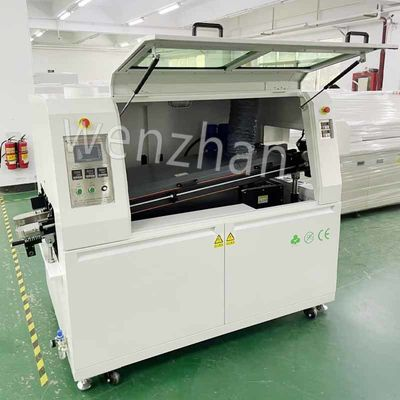
For a PCB Wave Soldering Machine to operate optimally, it must balance multiple variables simultaneously. This delicate balance includes the precise temperature ramp-up rate, the specific gravity of the flux, the exact height of the molten solder wave, and the conveyor speed that dictates dwell time. Sensors act as diagnostic tools. They continuously measure these physical variables against programmed baseline targets.
When sensors drift out of calibration, the bottom-line impact is immediate. A faulty temperature sensor can cause the preheat zone to underperform. This leaves viscous flux unactivated and results in cold solder joints. Conversely, an overactive heater can easily delaminate the substrate. These undetected failures inevitably lead to increased manual rework and costly unplanned machine downtime.
To combat these issues, modern equipment operates on a sophisticated closed-loop control system. Sensors serve as the input mechanisms, sending continuous electrical signals to the programmable logic controller. The controller instantly compares this real-time data to set parameters and makes micro-adjustments to actuators without requiring human intervention.
The preheating phase is critical for evaporating volatile flux solvents and preparing the board for extreme thermal exposure. Infrared and convection preheating zones typically utilize Type K thermocouples and resistance temperature detectors. These sensors offer exceptional accuracy and stability over time. Specifically, they ensure the board temperature ramps up gradually, usually at a controlled rate of 1 to 2 degrees Celsius per second. This gradual climb activates the flux properly while preventing severe thermal shock to fragile ceramic capacitors.
Moving to the solder pot, this zone represents the most thermally critical area of the machine. Heavy-duty sensors submerged directly in the liquid metal continuously monitor this harsh thermal environment. Maintaining the exact melting point is especially crucial for modern lead-free solder alloys like SAC305. These eco-friendly alloys operate within a much tighter thermal window than traditional leaded solders. When a room-temperature board enters the wave, it naturally acts as a heatsink. Submerged sensors must instantly detect this micro-drop in temperature and trigger the internal heating elements, such as those found in standard 250kg capacity solder pots, to stabilize the bath before the next board arrives.
Proper flux application is the absolute foundation of a reliable metallurgical bond. Inside the flux reservoir, float sensors and ultrasonic level sensors constantly monitor the liquid volume. They ensure the machine never runs dry during a high-speed production run. Furthermore, density sensors function as automated hydrometers to monitor the specific gravity of the liquid. As volatile solvents naturally evaporate, the chemical concentration changes. The density sensor detects this subtle shift and triggers an automatic dosing system to inject thinner.
Modern machines utilize highly precise atomized spray systems controlled by stepper motors. Optical and differential pressure sensors are integrated directly into the flux spray nozzle assembly to verify flow rates. These sensors confirm that a uniform, micro-fine mist of flux is applied exclusively to the bottom side of the board. If the pressure suddenly drops, the sensor alerts the system to a potential nozzle clog. This prevents skipped areas where un-fluxed copper fails to solder.
During continuous manufacturing, the equipment consumes a significant amount of solder alloy. To manage this depletion, machines are equipped with solder pot level sensors. These are often constructed from titanium or stainless steel conductive probes to withstand the corrosive nature of molten tin. They detect when the overall volume drops below a critical threshold. Once triggered, the sensor sends a signal to the automatic solder wire feeder, seamlessly replenishing the pot with fresh solid alloy.
The height and stability of the solder wave crest are arguably the most critical physical parameters. If the wave crest is too high, molten metal will flood over the top of the board and destroy top-side components. Wave height sensors utilize either non-contact lasers or mechanical contact probes to monitor the exact physical height of the molten crest. They feed this data back to the variable frequency drive controlling the impeller pump. This adjusts the motor speed in real-time to keep the wave perfectly steady.
To optimize material usage, a smart soldering machine does not run its flux sprayers and solder pumps continuously. Instead, it relies on a strategic network of photoelectric optical sensors located at the entrance, middle, and exit of the conveyor tunnel. By mapping the exact location of the board, the system can turn the flux sprayer and the solder wave impeller on merely milliseconds before the board arrives. This targeted actuation drastically reduces the consumption of expensive flux and minimizes dross formation.
The dwell time is strictly dictated by the conveyor speed, which typically ranges from zero to 1.8 meters per minute on standard automated lines. Rotary speed encoders attached to the conveyor motors monitor rotational movement. This ensures the board travels at the exact programmed pace, preventing component heat damage.
In addition, these entrance sensors facilitate vital synchronization with upstream factory machinery via standard communication protocols. For instance, the conveyor sensors communicate directly with upstream Axial Automated Insertion Equipment to smoothly pace the influx of loaded boards. This seamless data exchange signals upstream machines to hold or release components based on current internal capacity.
Many high-end automated machines are equipped with sealed nitrogen tunnels. Introducing inert nitrogen gas displaces oxygen over the solder wave, which drastically reduces the formation of solder dross and improves wetting characteristics. Highly sensitive oxygen analyzers are deployed within the tunnel to continuously sample the atmosphere. They measure the remaining oxygen levels in parts per million. If oxygen levels rise above the programmed threshold, the sensors regulate the nitrogen flow valves to open wider.
The heating of chemical flux generates volatile organic compounds that must be safely extracted. Differential pressure sensors are installed inside the exhaust stacks to monitor the airflow volume. Crucially, they ensure the exhaust draw is not overly aggressive. An excessive draft can inadvertently pull essential heat energy out of the pre-heat zones, causing the heating elements to overwork.
A standard automated wave soldering machine is designed for macro-level processing. Its sensor architecture is built to treat the entire underside of the board uniformly. Consequently, the sensors are calibrated to monitor broad environmental conditions within large chambers.
In stark contrast, specialized mixed-technology boards require a much more granular approach. An Offline Selective Wave Soldering Machine utilizes an entirely different micro-precision sensor array. Selective soldering targets single pins using a miniature solder fountain mounted on a robotic gantry. These machines employ fiducial recognition cameras and laser displacement sensors to achieve positioning accuracy as tight as plus or minus 0.05 millimeters.
| Feature Focus | High-Volume Wave Soldering | Offline Selective Soldering |
|---|---|---|
| Sensor Architecture | Macro-level monitoring for wide-area stability | Micro-precision mapping for targeted joints |
| Flux Application | Full-width atomized spray nozzles | Micro-dot drop jet fluxers |
| Thermal Control | Large 250kg solder pot with multi-zone preheat | Small 15kg to 20kg pot with localized nitrogen heating |
| Positioning Accuracy | Standard conveyor edge tracking | High-precision servo motors accurate to ±0.05mm |
Choosing the right sensor package depends entirely on your production environment. If you are running a high-mix, low-volume facility with double-sided surface mount components, a standard wave machine will likely cause thermal damage. Instead, you need the laser-guided precision of a selective soldering setup. The vision sensors in these machines actively compensate for board warpage, ensuring the miniature solder nozzle never collides with delicate components.
Conversely, for mass production of heavy power supplies or standard through-hole boards, a traditional wave soldering machine with a robust PID temperature control loop is the best choice. When selecting this equipment, ensure the machine features titanium dual-wave impellers and automated specific gravity flux sensors. These specific features drastically reduce the manual labor required to keep the process window stable during continuous three-shift operations.
Even the most advanced sensors will inevitably fail if they are obscured by the harsh byproducts of the soldering process. Establishing a strict routine cleaning protocol is mandatory. Optical sensors frequently become clouded by vaporized flux and must be wiped down with approved solvents daily. Similarly, titanium mechanical probes in the solder pot quickly become coated in conductive dross. Operators must carefully brush and scrape these level probes during routine maintenance shifts to remove oxidation.
Beyond immediate physical cleaning, internal sensors can experience thermal drift over time due to extreme heat cycling. It is critical to verify that the internal thermocouples are reporting accurate data against an independent standard. A basic preventative maintenance schedule should include weekly verification of flux density hydrometers and monthly runs of a third-party thermal profiler to verify pre-heat accuracy.
The true power of automated soldering equipment lies deep within its sensory nervous system. From managing the delicate pre-heat temperature curve to governing the precise conveyor speed, sensors act as the invisible operators keeping the entire complex process in range. Whether a facility is running a high-volume continuous line fed by upstream automated insertion equipment or executing highly specialized runs on a selective soldering system, understanding these critical sensors is the absolute key to achieving zero-defect manufacturing. Manufacturers should proactively evaluate their current equipment and explore modern machine upgrades to stay competitive. If you are looking to upgrade your production line with high-precision, sensor-driven equipment, explore the comprehensive range of professional assembly solutions at SMTWENZHAN to find the perfect fit for your factory floor.
Internal thermocouples and resistance temperature detectors should be verified against a known third-party thermal profiling tool at least once a month. Additionally, a formal factory calibration should be performed annually to ensure strict compliance with manufacturing standards and to maintain overall process integrity.
The most common cause of wave height sensor failure is the physical buildup of solder dross or baked-on oxidized flux residue directly on the sensor probe. Regular daily maintenance, thorough physical cleaning, and routine skimming of the solder pot are required to prevent this accumulation from insulating the probe.
While exact temperatures depend on the specific solder alloy and flux type, standard lead-free alloys like SAC305 typically require a solder pot temperature between 260 and 270 degrees Celsius. The preheat zone is usually configured to bring the board surface temperature to between 100 and 130 degrees Celsius before it hits the wave.
Selective soldering machines utilize advanced laser displacement sensors that scan the board surface in real-time along the Z-axis. If the sensor detects warpage, it feeds the exact deviation data back to the robotic gantry. The servo motors then automatically adjust the height of the solder nozzle to maintain a perfect distance from the target pins.
Yes, modern machines utilize advanced optical photoelectric sensors and integrated vision systems at the conveyor entrance. These sensors can detect board width, orientation, and physical presence. They automatically halt the conveyor process and trigger a system alarm if an alignment error is detected before the board enters the fluxing zone.