Views: 0 Author: Site Editor Publish Time: 2026-09-19 Origin: Site
An SMT line is a sequence of decisions, and nowhere is that clearer than in drone manufacturing. A flight controller board may carry a several-hundred-pin connector on one end and 0402 passives clustered around a gyro on the other. The same factory then runs an ESC board with heavy copper, and a gimbal driver with a mix of fine-pitch logic and mechanically robust interfaces. One line has to handle all of it, at batch sizes that shift week to week.
That is the engineering problem this article addresses. Rather than presenting a machine on its own, it walks the production route in order — print, place, reflow, inspect — and shows what each station must do for a drone PCBA, and how the Panasonic NPM-TT2 fits into that route as the placement station of a fully integrated line.
Constraint one: long boards and high layer counts punish conveyor stability. Drone PCBs are frequently elongated to match airframe geometry, and use enough layers to separate noisy power planes from sensitive IMU signal routing. Long, thick, high-layer-count substrates behave differently on a conveyor than a compact consumer board: they sag, they retain heat unevenly, and they resist sitting flat against the rail. A line specified for short boards will fight these panels at every station.
Constraint two: the connector population is the real placement bottleneck. Flight controllers and power distribution boards are dense in board-to-board headers, JST-style connectors, terminal blocks and shield frames. These are neither chips nor standard QFPs. They are tall, heavy and often arrive in trays or tubes rather than tape. Lines built purely for chip-shooting speed end up hand-placing them, which breaks the automation chain and injects human variance into the exact joints that must survive vibration.
Constraint three: batch economics do not forgive long changeovers. Drone builders iterate quickly. A frame revision, a new ESC rating or a payload swap can invalidate a board and force a new build within weeks. When every model change requires stripping the machine of feeders and rebuilding the setup from a cart, the changeover cost can exceed the production run itself. Material must therefore live on the machine in depth, not in a storage room.
A line that ignores these three realities will produce boards — but it will produce them slowly, with rework concentrated at connectors, and with a per-model overhead that quietly destroys margin.
The first station dictates the ceiling for everything downstream. Paste volume and registration set the window within which placement and reflow must operate; a print that is 15 % light on volume cannot be recovered by a better mounter.
For drone boards the challenge is the co-existence of very small apertures around the inertial sensor cluster and large, high-volume apertures for power pads, on the same stencil. A printer with closed-loop squeegee pressure and stable rail support is essential — the elongated panels described earlier must be held flat through the print stroke, and paste release from small apertures must remain consistent across the full panel length.
Practically, the print station must also introduce drone PCBA into the process as early as possible, so the operator can verify that the panel is correctly supported before the line runs at speed. Paste height monitoring at this stage is the cheapest defect detection in the entire factory.
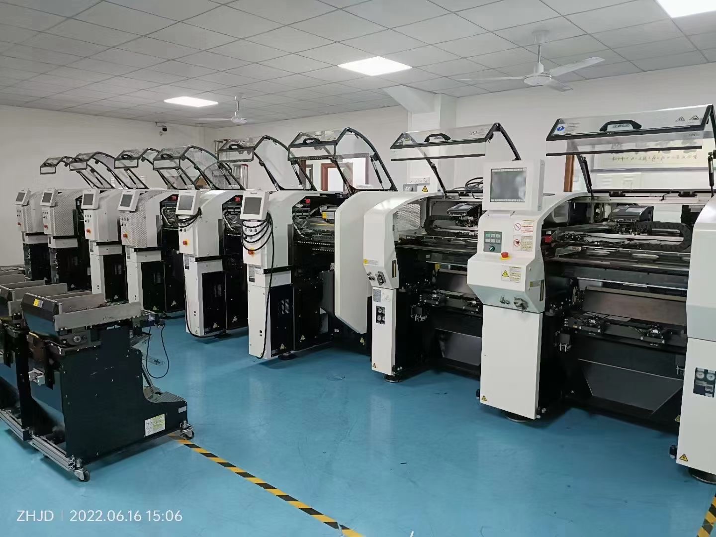
The Panasonic NPM-TT2 — Next Production Modular-Twin Tray II — is the placement heart of the line, and it is chosen precisely because of the second constraint above: connectors. It sits on the Panasonic NPM modular platform and uses a dual-gantry, twin-tray configuration.
Twin Tray is not a marketing term; it is the structural answer to odd-form components. Instead of forcing connectors into tape, the machine carries tray capacity directly, with up to 40 trays (20 front + 20 rear) and a per-side arrangement of 40 trays plus 26 fixed tape inputs — 92 inputs per side. Tray-based parts and tape-based chips therefore coexist on the same machine, which means a flight controller can be populated in one continuous pass rather than split between an automated line and a manual bench.
Feeder and tray positions are interchangeable, so as a design migrates from prototype to volume production — trays giving way to tape — the machine re-balances without new hardware. For engineers who have lived through a "connector hand-placement" caveat, this is the single most valuable property of the platform.
The NPM-TT2 accepts a lightweight 8-nozzle placement head and a 3-nozzle placement head V2 (100 N). They are complementary, not redundant:
Head | Throughput | Placement accuracy (Cpk ≥ 1) | Component range |
|---|---|---|---|
Lightweight 8-nozzle | 18,000 cph (0.20 s/chip) on PCB-size; 17,460 cph (0.21 s/chip) on M-size | ±40 μm/chip | 0402 chip (01005) up to L32 × W32 × T12 mm |
3-nozzle V2 (100 N) | 7,200 cph (0.50 s/chip); 5,900 cph (0.61 s/QFP) on PCB-size; 6,984 cph and 5,723 cph on M-size | ±40 μm/chip; ±30 μm/QFP; ±50 μm/QFP (under 12 mm) | 0603 chip up to L150 × W25 mm (152 mm diagonal) × T30 mm; BGA up to 80 × 80 mm |
The division of labour is deliberate. The 8-nozzle head clears the passive population at high tact speed, while the 100 N, 3-nozzle V2 head presses connectors, shields and large BGAs home with the force and placement tolerance those parts require. A connector that needs mechanical seating gets it without a second machine and without a second setup.
Material capacity is what converts flexibility into uptime. The NPM-TT2 supports tape widths of 4–56/72 mm on the 8-nozzle head and 4–56/72/88/104 mm on the 3-nozzle V2 head, with tray feeders up to 52, and feeder carts up to 120 positions using 4/8 mm tape. Stackable tube feeders cover axially-fed parts, with capacity for 12 single-tube positions on the tray feeder and 28 on the feeder cart. Compatibility with existing CM and NPM series smart feeders and nozzles means an operator's existing material library transfers to the machine.
Board formats are handled with equal range. In single-lane configuration the NPM-TT2 accepts L50 × W50 mm up to L510 × W590 mm; in dual-lane configuration, L50 × W50 mm up to L510 × W300 mm. On M-size formats, single lane spans L50 × W50 mm to L510 × W510 mm and dual lane L50 × W50 mm to L510 × W260 mm.
PCB transfer time is 4.0 s in single-lane operation and 0 s in dual-lane operation when the tact is 4.0 s or less — the second lane is being populated while the first is exchanging, so board transfer disappears from the cycle entirely. Independent dual-lane running allows two different board types to be produced on the same machine at the same time, and the lane mode can be switched to single-lane when a larger substrate needs the full width. For a drone builder running a flight controller and an ESC board in the same week, that independence is direct throughput.
Two further details matter on the floor. The pre-pick smart tray component detection function verifies tray parts before pickup, which cuts the unplanned stops that otherwise accumulate around tray-fed connectors. The pin-in-place lighting option supports visual confirmation during setup and inspection of seated pins. Physically, the machine occupies W1300 × D2798 × H1444 mm and weighs approximately 2690 kg, running on 3-phase AC200/220/380/400/420/480 V at 2.5 kVA with an air supply of at least 0.5 MPa at 200 L/min (A.N.R.).
Placement accuracy is only preserved if the thermal profile is right. A drone board with heavy power planes and a light sensor cluster has a genuinely uneven thermal mass — the same profile that fully reflows a ground plane can over-cook a small thermal-relief pad nearby.
The reflow station must therefore deliver a controllable, repeatable zone profile with enough heated length to bring the whole panel up evenly, and enough cooling capacity to bring it down without thermal shock to the connector bodies and plastic housings that dominate a drone board. Boards carrying tray-fed connectors are especially sensitive here: these parts are the first to suffer if the exit-zone cooling is too abrupt or too slow.
Because the line is configured as one flow, the reflow profile can be developed against the same panels that the printer and NPM-TT2 will run, rather than against a proxy coupon. That is a small-sounding advantage with a large effect on first-article approval time.
The final station converts the line from "producing" to "proving." Drone electronics carry consequences: a lifted lead on a motor driver is not a warranty issue, it is a flight-safety issue. Inspection therefore has to cover solder joints, component presence and polarity, and the seated condition of connectors — including the ones that were tray-fed because tape could not carry them.
Automated optical inspection at the end of the line also closes the quality loop back to the earlier stations. Recurring solder-volume deviations trace back to printing; recurring offset at a particular connector footprint traces back to placement and feeder presentation. Without an in-line inspection node, the line produces data that nobody acts on.
A four-station line is not a shopping list; it is a configuration. Every element — printer, mounter, oven, inspector, plus the conveyors between them — has to be matched to the intended panel, the target output and the available floor space, or the line will be unbalanced on day one.
Our professional team provides complete SMT production line customization and turn-key delivery: we take your PCB dimensions, layer count, component mix and target cycle time, and design the line configuration around them, then supply, integrate and commission it. The Panasonic NPM-TT2 is specified into the line at the placement station with its head configuration, feeder and tray arrangement and lane mode chosen to match your board, not a generic template. Commissioning includes line integration and operator hand-over, so the line enters production with a validated profile and a trained team.
Beyond the physical line, we offer customized service packages structured around how you actually operate. These range from turn-key installation and calibration programmes for new facilities through to ongoing performance programmes for established lines — including periodic accuracy audits, feeder and nozzle maintenance scheduling, software support and spare-part planning mapped to your production calendar. Because the NPM-TT2 is compatible with CM and NPM series smart feeders and nozzles, service programmes can also cover your existing material stock rather than demanding a wholesale replacement.
The configuration described above suits any manufacturing environment where elongated boards, connector-heavy designs and mixed batch sizes occur together. Five industries see this combination most often:
Drone and UAV manufacturing — flight controllers, ESC boards, gimbal drivers, power distribution modules, and the ground-station hardware that supports them.
Industrial control and automation — PLC I/O modules, servo drives and machine controllers, which share the drone pattern of long boards, many terminal connections and moderate batch sizes.
Automotive electronics — body control modules, sensor interface boards and auxiliary controllers, where connector robustness and traceable quality are contractual requirements.
Power electronics and energy storage — BMS boards and inverter control cards, with heavy copper, tray-fed modules and demanding thermal behaviour.
Medical and instrumentation electronics — where odd-form parts, low volumes and inspection-heavy flows make setup efficiency and connector integrity the dominant cost drivers.
In each case the same logic applies: the line only performs if printing, placement, reflow and inspection are specified as one system.
Drone PCB assembly rewards lines that were designed for it and punishes lines that were merely adapted to it. The difference lives in the details — whether connectors are placed automatically or by hand, whether a model change costs a cart rebuild or nothing at all, whether board transfer time contributes to the cycle or has been engineered out of it.
The Panasonic NPM-TT2, specified as the placement station of a four-station full-automatic line, answers those questions with twin-tray capacity, a 100 N three-nozzle V2 head for the parts that need force, 92 inputs per side for mixed-batch depth, and 0 s dual-lane transfer. Around it, printing defines the process window, reflow preserves it, and inspection proves it.
Tell us your board dimensions, layer count, component mix and target output — our professional team will return a configured line proposal, not a catalogue entry.