Views: 0 Author: Site Editor Publish Time: 2026-10-10 Origin: Site
Mastering wave soldering equipment operation is an absolute necessity for ensuring high-quality printed circuit board production. This foundational manufacturing process remains vital for mass-producing through-hole and mixed-technology electronics at scale. The stakes on the factory floor are undeniably high. Incorrect operation or a casual approach to safety protocols can instantly trigger costly defects like solder bridging or cold joints. Worse still, poor parameter setup can lead to catastrophic equipment damage and severe workplace hazards involving molten metal. This comprehensive engineering guide provides a detailed walkthrough of the startup process, the exact parameters required for flawless soldering, essential safety guidelines, and the routine maintenance practices that keep production lines running smoothly.
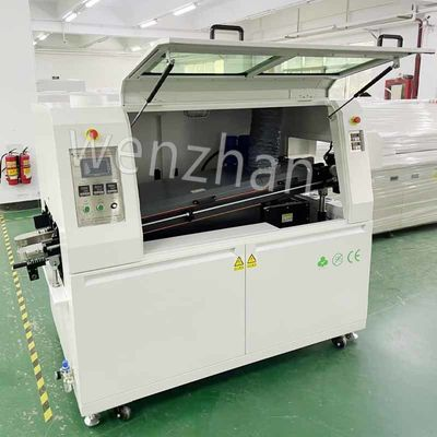
A wave soldering machine operates as a large-scale, highly automated industrial system engineered specifically for mass electronics manufacturing. Its core function is to permanently bond through-hole components and bottom-side surface-mount parts to a circuit board with speed and reliability. Inside the heated tank of the machine, a motorized pump continuously forces molten solder upward through a specialized nozzle. This generates a dynamic, standing wave of liquid metal. As the automated conveyor guides the PCB over this tank, the bottom surface of the board gently grazes the wave. Capillary action instantly draws the liquid solder up into the plated through-holes, forging hundreds of reliable electrical and mechanical connections in mere seconds.
In the landscape of modern electronic manufacturing, purely through-hole boards are increasingly rare. Most commercial designs combine through-hole components with densely packed surface mount technology. Integrating an SMT assembly wave soldering machine into the broader production line guarantees high throughput for these complex mixed-technology boards. Take industry-standard equipment like the WZ-250 series for example. These machines typically feature dual-wave technology—a turbulent chip wave followed by a smooth main wave—and robust preheat zones capable of handling PCB widths up to 250mm. Positioned immediately after the reflow oven, this system manages the remaining through-hole parts. Operators often utilize specialized heat-curing adhesives to secure bottom-side surface mount components. This allows them to pass directly through the molten solder wave without detaching or shifting.
While both methodologies apply molten metal to circuit boards, their operational scale, fluid dynamics, and automation levels differ drastically. A continuous wave system leverages a motorized conveyor, making it the ideal choice for high-volume, uninterrupted production runs. In contrast, a PCB solder dip machine functions as a manual or semi-automated batch system. Equipment like the WZ-550 dip machine is engineered for smaller footprints and cost-effective operations. During a dip process, an operator or robotic arm carefully lowers the entire board into a static, calm bath of molten solder. Because it lacks a dynamic flowing wave, the dip method is generally reserved for low-volume prototyping, specialized rework, or tinning component leads prior to final assembly.
| Equipment Type | Ideal Application | Automation Level | Core Advantage |
|---|---|---|---|
| Standard Wave Soldering | High-volume mixed technology boards | Fully Automated | Maximum throughput and consistency |
| Selective Soldering | Dense boards with sensitive components | Programmable CNC | Pinpoint accuracy without thermal damage |
| Solder Dip Machine | Prototyping, rework, lead tinning | Manual / Semi-Auto | Low cost and minimal footprint |
Long before initiating any power sequence, operators must execute a meticulous visual inspection of the hardware and the surrounding facility. Begin by examining the conveyor rails and titanium transport fingers. Even a tiny metallic burr or residual solder splash can cause a board to jam mid-process. You simply cannot afford that kind of line downtime. Next, listen for the distinct hum of the exhaust fans and verify that the ventilation system is pulling adequate negative pressure. Proper airflow is non-negotiable for extracting hazardous flux fumes. Finally, scan the heating zones to ensure no loose panels, unfastened wires, or stray tools are resting near the high-temperature elements.
Flawless execution relies heavily on chemical and material consistency. First, open the pot enclosure and inspect the solid solder level. The metal must sit within the manufacturer recommended depth range. If the reservoir appears low, carefully slide fresh, compatible solder bars into the chamber before activating the heaters. Moving to the chemical side, evaluate the fluxing system. Operators must measure the specific gravity of the flux using a hydrometer. As the shift progresses, volatile solvents evaporate, thickening the liquid. If the density measures too high, precise amounts of thinner must be introduced. This restores the optimal chemical balance required to effectively strip away copper oxidation.
Working near hundreds of kilograms of liquified metal leaves zero room for error. Operators must systematically test every emergency stop button, ensuring they instantly sever power to the pumps and convection heaters. Confirm that all thermal guards, splash shields, and transparent safety interlock panels are firmly latched. Bypassing these localized safety features for the sake of convenience invites catastrophic equipment failure and severe personal injury.
The startup ritual commences by engaging the main power disconnect and booting the primary control interface of the machine. Immediately following this, the operator activates the solder pot heaters. Because industrial crucibles hold immense volumes of metal, the thermal transition is intentionally gradual. It typically takes one to two hours to convert the solid alloy block into a fully molten, thermally stable liquid pool. During this waiting period, one strict operational rule applies. Never activate the solder pump. Forcing the impeller to turn while the metal remains in a semi-solid slush state will instantly shear the drive shaft or burn out the pump motor.
Once the system achieves thermal equilibrium, the physical soldering journey unfolds across four distinct, sequential stages. The fluxing stage occurs first. As the bare board enters the tunnel, a pressurized spray nozzle or porous foam cylinder coats the underside with a precise, micro-thin layer of liquid flux. This chemical agent aggressively attacks surface oxidation, preparing the copper pads for metallurgical bonding.
Following flux application, the board glides into the preheating zone. Here, banks of infrared or convection heaters serve a dual purpose. They evaporate the volatile solvents trapped within the flux, preventing explosive outgassing when the board hits the molten metal. Furthermore, they gently elevate the core temperature of the board to prevent thermal shock from cracking sensitive ceramic capacitors.
The climax of the operation is the solder wave itself. As the preheated board passes over the crucible, a turbulent chip wave forcefully drives solder into the tight crevices between surface mount components. Immediately after, a smooth, glassy main wave washes over the board. This finishes the joints and utilizes fluid dynamics to pull away excess metal, thereby preventing bridges. Finally, the cooling stage takes over. High-volume fans blast ambient air across the exiting board, rapidly freezing the liquid solder to form a tight, fine-grain metallurgical structure while preventing the substrate from warping.
The speed of the conveyor belt serves as the master clock for the entire process. It directly dictates the dwell time, which is the exact number of seconds the board remains submerged in the molten wave. Standard industrial speeds typically hover between 1.0 and 1.5 meters per minute, yielding an ideal dwell time of two to four seconds. Pushing the speed too high starves the through-holes of solder, resulting in weak, hollow joints. Conversely, a sluggish pace subjects the board to excessive thermal stress. Building on this, the conveyor is intentionally pitched at an incline, usually spanning 4 to 9 degrees. This specific angle harnesses gravity, encouraging excess liquid solder to cleanly peel back off the trailing edge of the board as it exits the wave.
Calibrating the preheat parameters requires a nuanced understanding of board thickness, component mass, and flux chemistry. For standard FR4 assemblies, the topside temperature of the board measured just moments before it touches the wave should reach between 90 degrees Celsius and 130 degrees Celsius. Water-soluble fluxes generally demand higher activation temperatures compared to milder no-clean variants. Deploying a thermal profiling tracker remains the most empirical method to guarantee the preheat zones are delivering the correct thermal curve.
The target temperature of the molten bath is dictated entirely by the specific alloy composition. Traditional tin-lead alloys flow beautifully at pot temperatures between 245 degrees Celsius and 250 degrees Celsius. Modern lead-free alternatives possess higher melting points, forcing operators to elevate pot temperatures into the 260 to 270 degrees Celsius range. Meanwhile, the operator dictates wave height by adjusting the pump motor revolutions per minute. The golden rule is to set the wave height so that it immerses roughly one-half to two-thirds of the total thickness of the board. A wave set too low physically misses the pins. An aggressive, high wave will flood the topside of the board, destroying components instantly.
As consumer electronics push relentlessly toward miniaturization, board real estate has become incredibly dense. When engineers design a board featuring a handful of through-hole connectors surrounded by tightly packed, highly sensitive bottom-side micro-components, running the entire assembly over a broad solder wave is no longer viable. The massive thermal wave would simply melt the surface mount joints and wash the tiny parts away. To solve this manufacturing bottleneck, facilities transition to a PCB Welding Selective Wave Soldering Machine. Instead of a monolithic wave, this advanced offline system utilizes a miniature, computer-controlled solder fountain that darts across the board, applying molten metal exclusively to targeted through-hole pins.
The operational mindset shifts dramatically when moving from standard to selective systems. Traditional wave soldering relies entirely on global parameters. You set one continuous conveyor speed, one overarching preheat profile, and a single wave height applied uniformly to the entire board. Selective soldering, however, requires meticulous offline software programming. Technicians must map out the three-axis coordinates for every individual joint. The robotic nozzle can dynamically adjust its dwell time, approach angle, and solder volume on a pin-by-pin basis. Specifically, selective nozzles are frequently shrouded in localized nitrogen gas to eliminate oxidation at the point of soldering. This is a highly efficient feature rarely applied to the massive, open-air baths of standard machines.
The landscape of automated soldering is rapidly evolving, driven by the principles of smart manufacturing and rigid environmental compliance. Modern facilities are increasingly moving away from manual parameter checks. Instead, they are opting for integrated smart sensors that monitor flux specific gravity, preheat thermal curves, and wave heights in real-time. This shift toward data-driven operation minimizes human error and allows for predictive maintenance, alerting operators to degrading pump impellers before a catastrophic failure occurs.
Furthermore, the industry is seeing a massive push toward enclosed nitrogen tunnel wave soldering. By displacing oxygen in the soldering zone, nitrogen drastically reduces dross formation and improves the wetting capabilities of lead-free solders. As environmental regulations tighten globally, metallurgists continue to refine lead-free alloy compositions. These new alloys aim to lower melting points and reduce the aggressive copper dissolution rates that plague older lead-free baths, thereby extending the lifespan of both the solder pot and the circuit board substrate.
Interacting with machinery that continuously pumps hundreds of kilograms of liquified metal at 260 degrees Celsius presents profound burn hazards. Consequently, safety protocols must be treated as absolute law on the factory floor. Operators are required to wear mandated personal protective equipment at all times. This arsenal includes high-temperature, heat-resistant gloves extending past the wrists, heavy-duty flame-retardant aprons, and closed-toe industrial footwear. Most importantly, safety goggles or full-face shields must be worn to deflect unpredictable micro-splashes of spitting flux or molten alloy.
When liquid flux meets extreme heat, it instantly vaporizes, generating volatile organic compounds and dense rosin fumes. Inhaling these byproducts poses severe respiratory risks, including the development of occupational asthma. Maintaining a professionally calibrated exhaust and ventilation system is a critical safety pillar. Facility managers must routinely inspect the exhaust hoods and ductwork. They must guarantee that adequate negative pressure is constantly drawing hazardous vapors away from the breathing zone of the operator and expelling them safely outdoors.
Replenishing the solder pot demands calculated, steady movements. When adding solid solder bars, operators must grip the metal with heavy tongs and lower it into the bath at a glacial pace. Dropping a heavy bar will displace the liquid, triggering a dangerous splash of molten metal. Similarly, tools used for maintenance, such as dross skimmers, must be bone dry. Introducing even a single drop of ambient moisture into a hot solder bath causes the water to instantly flash-boil into steam. This results in a violent, explosive eruption of liquid metal.
Solder bridging manifests when a web of excess solder stretches across two or more adjacent pins, creating a disastrous electrical short circuit. This defect frequently stems from fluid dynamics that fail to separate properly. The conveyor speed might be too rapid, rushing the board out of the wave before the solder can drain. Alternatively, a wave height set too high creates turbulent splashing. To rectify this, operators should systematically verify the flux density, slightly reduce the conveyor speed, and ensure the conveyor incline is steep enough to let gravity pull the excess metal away.
When solder fails to climb all the way up the plated through-hole barrel to the topside of the board, the joint is deemed mechanically weak and electrically unreliable. This poor penetration is almost universally a thermal issue. If the preheat temperature is too low, the cold substrate acts as a massive heat sink, freezing the liquid solder mid-climb. To resolve this, technicians must increase the preheat zone temperatures, ensuring the board is thoroughly thermally soaked. They must also verify that the dwell time in the wave is long enough to allow capillary action to complete its job.
Solder icicles appear as sharp, stalactite-like protrusions hanging menacingly from the bottom of component leads. These spikes form when the liquid metal freezes too rapidly as the board exits the wave, preventing a smooth, rounded joint from forming. The root cause is typically a solder pot temperature that has dipped below the operational threshold of the alloy, or an incorrect conveyor peel-off angle. Operators must check the crucible with an external thermocouple to confirm the temperature and adjust the cooling fans to ensure they are not prematurely chilling the wave itself.
The bedrock of consistent, high-yield machine operation is disciplined daily maintenance. At the conclusion of every shift, operators must perform dross removal. Using a specialized, perforated titanium scoop, technicians carefully skim the dark, oxidized powder from the surface of the molten pool. Leaving excessive dross in the tank insulates the heat and severely disrupts wave fluid dynamics. Following this, the flux spray nozzles must be thoroughly purged with isopropyl alcohol to dissolve sticky resins that cause erratic spray patterns. Finally, wiping down the conveyor fingers prevents flux buildup from jamming the transport rails.
Looking beyond the daily wipe-downs, deeper mechanical servicing ensures long-term operational stability. On a monthly basis, maintenance crews should extract the wave pump impellers. Scrubbing away hardened dross and solder buildup from the impeller blades guarantees a smooth, vibration-free wave height. In addition, applying high-temperature synthetic grease to the conveyor drive chains prevents the belt from shuddering. A mechanical hiccup here easily fractures cooling solder joints. Quarterly, a physical sample of the molten bath must be mailed to a metallurgical laboratory. As boards pass through the wave, microscopic amounts of copper dissolve into the pot. If this copper contamination breaches strict industry thresholds, the bath becomes sluggish and must be partially drained and replenished with virgin alloy.
Achieving mastery in wave soldering equipment operation requires a blend of rigorous preparation, deep technical knowledge, and unwavering discipline. Precise manipulation of thermal parameters and conveyor speeds remains the ultimate secret to unlocking high-yield, defect-free manufacturing runs. Simultaneously, strict adherence to safety protocols and exhaust management consistently shields operators from severe workplace hazards. By committing to a structured routine maintenance schedule, facilities can prevent sudden mechanical failures and extend the life of their capital equipment. While modern automated systems are highly advanced, it is the profound understanding of the underlying chemical and thermal dynamics that guarantees true production success. If you are looking to upgrade your assembly line with reliable, high-performance equipment, evaluate your specific volume and board density needs. Explore the robust selection of automated and selective soldering solutions at smtwenzhan.com to find the exact machinery that aligns with your production goals.
The optimal temperature is dictated entirely by the specific solder alloy utilized in your production process. Traditional tin-lead solder operates flawlessly when the pot is maintained between 245 degrees Celsius and 250 degrees Celsius. In contrast, modern lead-free alloys, which possess inherently higher melting points, require the crucible temperature to be elevated to a range of 260 to 270 degrees Celsius. Running the bath too cold results in poor hole penetration and icicles, while excessive heat can scorch the flux and delaminate the pads.
Dwell time defines the exact duration that a specific section of the circuit board remains submerged in the molten solder wave. For standard operations, the ideal dwell time falls strictly between 2 and 4 seconds. This brief window provides ample opportunity for thermal transfer and capillary action to pull the solder up the plated through-holes, while remaining short enough to prevent heat damage to sensitive electronic components. Operators control this critical metric by adjusting the speed of the motorized conveyor.
Dross, the unavoidable layer of oxidized metal that forms on the surface of the molten bath, must be skimmed at least once per production shift, or roughly every eight hours of continuous operation. Allowing thick layers of dross to accumulate chokes the pump mechanics, causes turbulent wave heights, and frequently leads to oxide particles becoming trapped inside the final solder joints. Operators must use a specialized perforated tool to sift the dross, ensuring usable liquid solder drains back into the pot.
Solder balls are tiny spheres of solder that stick to the solder mask or laminate after the board exits the wave. They are typically caused by explosive outgassing. If the preheat temperature is too low, the volatile solvents in the flux do not fully evaporate before hitting the 260-degree molten wave. The rapid boiling of these trapped solvents causes the molten solder to spit and scatter across the board. Adjusting the preheat profile to ensure complete solvent evaporation is the most effective solution.
Flux application is controlled by managing both the volume and the specific gravity of the chemical. In modern spray fluxers, operators program the spray nozzle pressure and traverse speed to deposit a micro-thin, uniform layer. Throughout the shift, operators must frequently check the specific gravity of the flux using a hydrometer or automated sensor. If the flux becomes too thick due to solvent evaporation, thinner must be added. If too much flux is applied, it creates a sticky residue and increases the risk of fire in the preheat zone.
A selective soldering system is deployed when a circuit board features a highly complex, double-sided layout where sensitive surface-mount components are located dangerously close to through-hole pins. Passing such a dense board over a massive, traditional solder wave would melt the bottom-side joints and wash the components away. The selective machine solves this by utilizing a programmable, miniature solder nozzle that targets individual pins with pinpoint accuracy, completely bypassing the surrounding architecture.
Operating industrial equipment containing hundreds of kilograms of liquified metal at extreme temperatures mandates strict personal protective equipment. Operators must wear full-face shields or wrap-around safety goggles to protect their eyes from sudden flux spits or molten metal splashes. Heavy-duty, heat-resistant thermal gloves that extend up the forearms are required to prevent severe contact burns. Furthermore, workers should wear flame-retardant aprons and ensure the facility exhaust system is actively pulling hazardous rosin fumes away from their breathing zone.